Last week National Grid ESO announced that it has begun to use a novel new tool for measuring grid inertia.
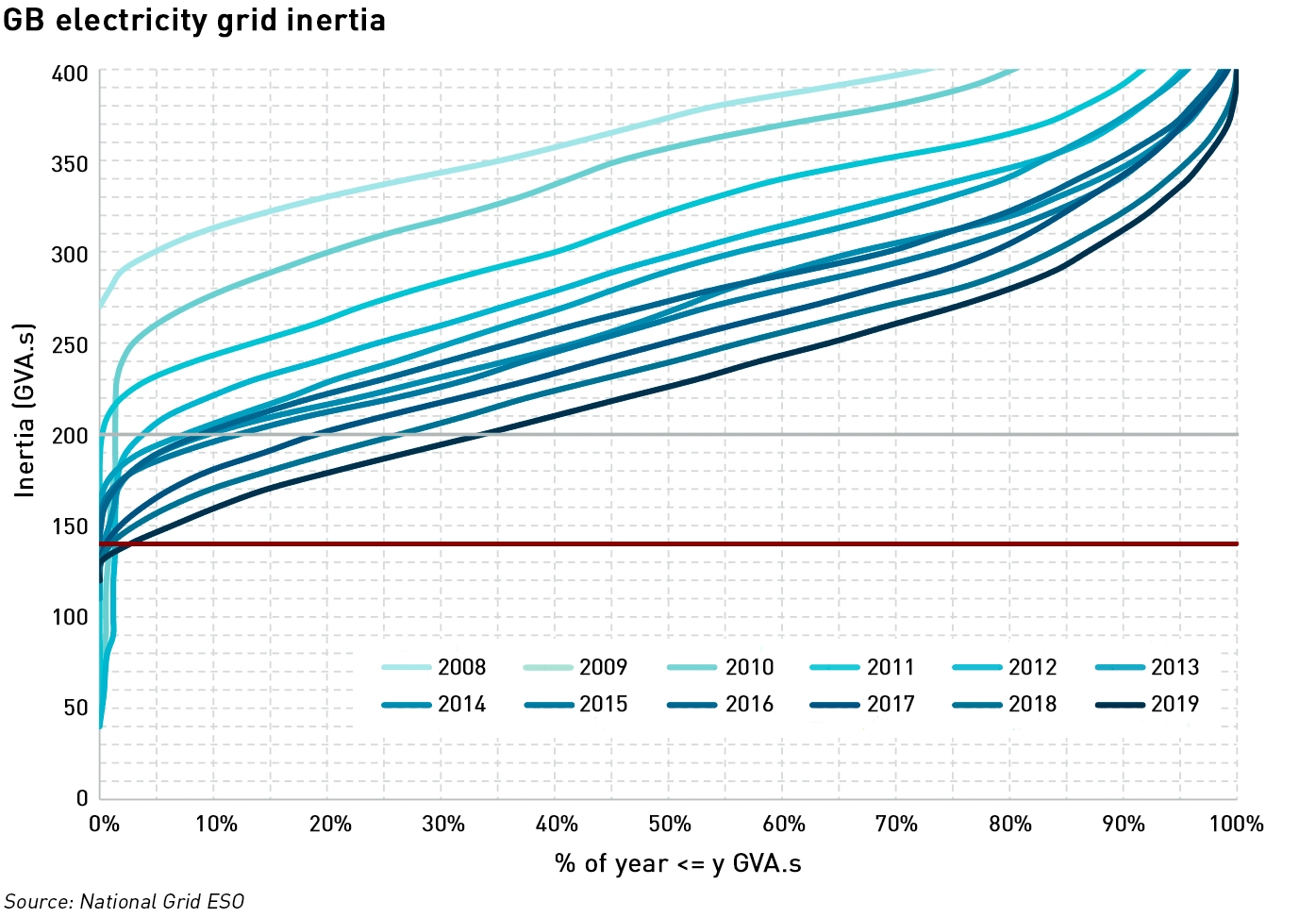
One of the challenges of managing an electricity system with a large amount of intermittent generation is maintaining grid frequency within operational tolerances. If supply and demand become unbalanced which can easily happen as wind speeds fluctuate from moment to moment or clouds pass in front of the sun, the voltage of the system begins to fluctuate – when the demand exceeds supply, the system frequency will fall, and vice versa. The rate of change of frequency fall will depend on the initial power mismatch and level of system inertia, where system inertia is the degree to which the system resists changes in inertia.
In a conventional electricity system, the frequency is determined by the rate at which the turbines in power stations turn: in a 50 Hz system, turbines rotate in synchronicity at 3,000 RPM. Not only do these turbines determine the frequency, but as they are very large, heavy objects, they resist changes to their angular momentum and hence they dampen changes in system frequency.
Renewable generation is generally not synchronous, so not only does its intermittency contribute to supply and demand imbalances, it does not provide any inertia. Where renewables have displaced conventional generation, this effect is magnified and lack of inertia becomes a problem.
In theory, electricity grids can safely operate with up to 75% of non-synchronous generation – above this level inertia is deemed too low to maintain stability. Since de-carbonised electricity systems can be expected to have high penetration of intermittent renewable generation, this is a potentially limiting factor. While nuclear power is both low carbon and a source of inertia, it’s very expensive.
New approaches have been taken to mitigating falling inertia, such as synchronous condensers, but since measuring inertia is difficult, its management is that much harder.
Why is it important to measure inertia accurately?
Without an accurate measurement of inertia, transmission system operators (“TSOs”) curtail renewable generation, for example, Irish TSO Eirgrid has a system non-synchronous penetration limit of 65%. Clearly, in a world where Governments are keen to see greater use of renewable generation to support environmental objectives, curtailment of renewable output is undesirable, and there is a need to find a way to lower the amount of conventional generation required for grid stability.
Traditionally there have been three ways of estimating the inertia of an electricity grid: summing the inertia constants from transmission-connected generation; calculating the Rate of Change of Frequency (“RoCoF”) during large frequency excursions, and calculating inertia based on power events throughout the day.
Summing the inertia constants from transmission-connected generation
The inertia constant (H) for large generators is known from manufacturer specifications. The inertia constants of all large generators which are outputting to the grid at any time (known by recording the breaker status in the SCADA system) can be summed together giving a continuous view of supply-side inertia. However it ignores any demand-side inertia, such as that from CHP engines or directly-connected motors – in the UK, demand-side inertia can be up to 30% the total system inertia, so ignoring it, or assuming it to be a constant value, leads to significant errors in the determination of inertia.
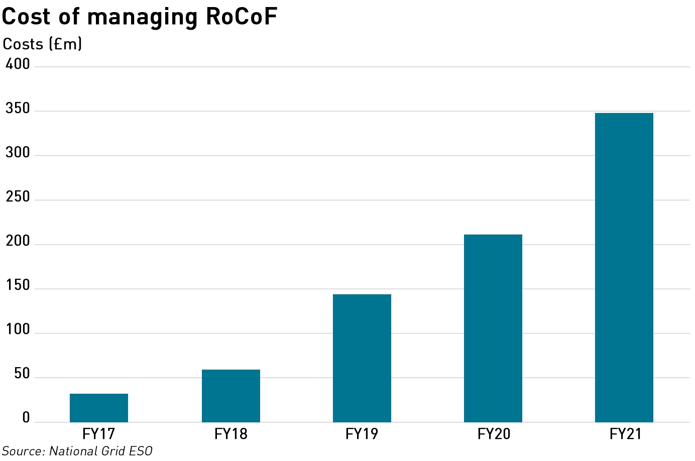
Calculating the Rate of Change of Frequency
During a large frequency excursion, inertia can be calculated from the amount of power loss and the resultant Rate of Change of Frequency using the Swing Equation methodology. (In the most basic sense a generator is one magnet rotating while inside the influence of another magnet’s magnetic field. The generator consists of stationary magnets – the stator – which create a powerful magnetic field; and a rotating magnet – the rotor – which distorts and cuts through the magnetic lines of flux of the stator, generating electricity. When there is a sudden change in the loading of the system, the rotor will accelerate or decelerate with respect to the synchronously rotating stator field, and this movement, or “swing” is described by the Swing Equation.) This takes account of demand-side inertia, but only provides an instantaneous view of total inertia, and it relies on there being an instantaneous loss of power. It can also be difficult to determine exactly when a frequency event started, which obviously effects the value of RoCoF.
Calculating inertia based on power events
This method is similar to the RoCoF method but rather than measuring the effect of occasional large power losses, it uses the small perturbations that occur throughout the day. Extensive measurements of power withing the SCADA system are required, and these power movements must be accurately measured if the inertia calculation is to be reliable. This requires the installation of expensive equipment throughout the network. It is also difficult to control for the actions of frequency control measures on the grid.
Overall, these approaches are limited either by providing an incomplete or potentially inaccurate measure of inertia, or only providing a snapshot during rare network events. They do not provide TSOs with reliable, real-time visibility of inertia, leading them to take a conservative approach to curtailment of renewable generation, and they do not allow TSOs to gain insights into how more non-synchronous generation can be safely integrated, beyond the addition of new sources of inertia such as synchronous condensers.
How does the new inertia measurement tool work?
 National Grid ESO is working with Reactive Technologies, using its Grid Matrix service to measure inertia. The system uses a large ultra-capacitor located in Teesside to send pulses of power through the electricity grid. These pulses allow grid inertia to be observed in a way that is analogous to the way that pulses of sound are used in sonar – their effect on grid frequency allows the level of inertia to be measured accurately in real time.
“The commercial adoption of Grid Metrix by National Grid is a significant milestone in the journey of our technology from a conceptual innovation to a proven and fundamental grid management solution,”
– Marc Borrett, chief executive, Reactive Technologies
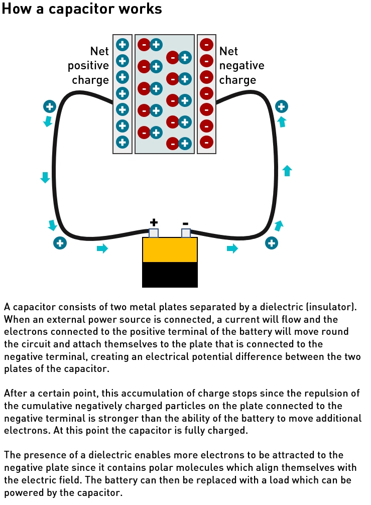
The 5 MW capacitor, constructed by Spanish technology group Ingeteam, is the largest continuously operating grid-scale capacitor in the world. Capacitors effectively store electricity, and while they generally hold much less charge than chemical batteries, their response times are faster and they have a longer life span. This makes them more suitable for this type of application than a chemical battery would be.
The approach developed by Reactive Technologies uses the capacitor to deliver a small power change in the network (<10 MW) which makes very small (c 0.0005 Hz) changes in frequency.
High-speed measurement units distributed around the grid observe these minute changes in frequency and report raw frequency and voltage data to an Analytics Server via a secure cloud connection.
Swing Equation methodology along with signal processing innovations allow these data to be interpreted to provide an accurate view of inertia in real time. The impact of the small input frequency changes is larger in areas lower inertia, allowing for even greater accuracy in inertia measurement when it is most critical.

The technique appears to be a small-scale version of the RoCoF measurement approach described above, except that rather than wait for a large change in system frequency, the system creates many much smaller changes whose impact the measurement units are then able to interpret.
GE inertia measurement and forecasting system
National Grid ESO is also using an inertia measurement and forecasting system from GE Digital. This approach measures effective inertia non-intrusively and on a regional basis using measurements of grid frequency and power flows on a 20ms timescale. Initially the GB grid has been divided into four regions, with the system capturing oscillations between regions through examining frequency and power flow changes. A machine learning forecasting model uses live operational data for calibration and integrates control room systems for demand forecasts and generation data.
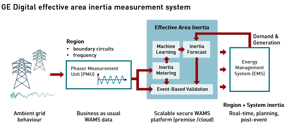
Effective Inertia captures not only the physical inertia from rotating synchronous generation but also the inertia-like effects of the non-synchronous generation and passive responses from domestic and industrial demand.
.
The Government intends for the amount of intermittent renewable generation on the electricity system to increase significantly. Not only does National Grid ESO need to manage the energy fluctuations that result from that intermittency – ie the ability to meet demand at all times – it also needs to manage the frequency impact since frequency deviations away from 50 Hz harm the stability of the grid and can lead to load shedding. The ability to measure inertia in real time will help NG ESO to increase its understanding of grid behaviour under different conditions enabling a smoother integration of intermittent generation and potentially a reduction in curtailments.


A very interesting and positive piece. This development will indeed enable NGSO to see how close they are to the cliff edge and to walk a little closer. It does not help them move away or question why they are walking so close.
Inertia is one of many interesting and esoteric technical issues associated with large volumes of non-synchronous intermittent generation, however more fundamental and simpler issues exist. When windy how will the 40GW of additional off-shore wind in the 10 point plan supply a customer requirement of only 20GW and when calm on a winter evening how will a customer demand of 50GW be supplied. Batteries and back-up generation are the often quoted glib answer but has this been been modelled and analysed in terms of costs and resulting CO2 emissions.
I competely agree about the need to manage to energy side of intermittency, and that being a much bigger problem. I just wanted to write a bit of a tech update…this blog was always supposed to include commentary on new energy innovations as well as market and regulatory developments – obviously the latter have been more of a priority recently, but it’s nice to be able to write about something that’s founded in science and not politics.
The other side if this coin is using grid batteries to provide synthetic inertia. I wonder how that programme will go now that we have record lithium carbonate prices that must surely dent the economics. Added to Timera’s assessment that it will not be long before battery revenues for Dynamic Containment start being cannibalised, we could see that we will be able to measure, but not necessarily to react.
https://timera-energy.com/changes-to-uk-battery-ancillary-revenues/
I welcome your update on technology. The solution will need to come from a planned engineered approach not market structures and a narrow brand of economics. Managing the energy side and other power system technical issues may mean that some solutions are not as cheap and effective as they superficially appear nor others as expensive.
With respect to your point about renewable intermittency, my understanding is there is only one solution on the horizon at the moment and that is you need to maintain gas generation capacity as a backup for renewables, which in turn means that as you up the amount of renewable capacity in the system (putting grid stability issues to one side!) you have to write-off a proportion of the capex and down time on gas, and at some point you’ve got you’ve got to rejig the energy market to support this backup gas capacity. The most optimistic forecast price for battery storage I’ve seen is $10/kwh which is a couple of orders of magnitude more expensive than firm generation. Pumped hydro might just be price competitive but then there are long lead and payback times and also ecological concerns limiting its attractiveness. There is an interesting proposal by a company called Xlink to build a combined solar and wind farm with battery backup in Morocco with a HVDC cable to the UK aiming at a cfd at under £50/mwh which they claim will effective generate “firm” renewable energy.
Thank you for another excellent article – you’ve described a very relevant topic for me and my colleagues. As rotating equipment engineers, with a product that allows generators to spin with a prime mover on standby, understanding how inertia can be measured (and it’s commercial value/how it is paid for) is key for us. Thanks for your previous mention … https://watt-logic.com/2021/02/15/synchronous-condenser/. I have never seen all of these measurement techniques so the link to this post has been passed around the world! Now can you explain the commercial bit please?!
I love this blog so much. Every article is outstanding.