Last week there was a widespread blackout across Iberia which also briefly affected the south of France. All power was lost on the peninsula and it was many hours before it was fully restored after a rare black start. Eight people are reported to have died – one in Portugal and seven in Spain – as a result of the blackout, highlighting the seriousness of the situation.
What happened
At 12:33 the Spanish grid experienced an as yet un-identified fault followed 1.5 seconds later by what appears to be a large trip. This caused frequency instability. 3.5 seconds later, the Iberian Peninsula grid disconnected from the rest of Europe, tripping the interconnectors to France – rated at 2.5 GW. All nuclear reactors connected to the grid also tripped off.
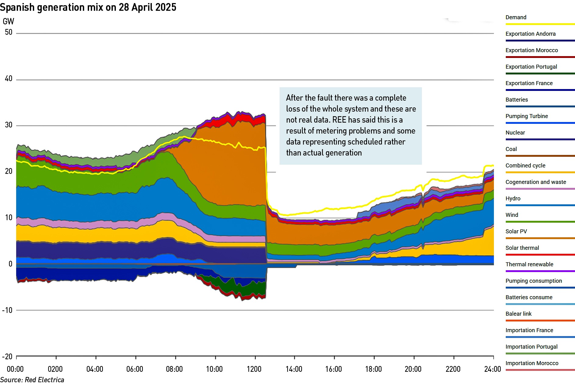
Although the chart indicates 10 GW of generation available after the trip, this reflects scheduled output, not real output. The grid went to zero and a full black start was required which took until the following morning to complete.
The cause of the initial fault has not been disclosed, although Spanish grid operator Red Eléctrica de España (“REE”) almost certainly would have known within hours if not minutes what happened. There has been a good deal of speculation, from cyber attacks to rare atmospheric phenomena (the Portuguese grid operator, Rede Eletrica Nacional (“REN”) apparently suggested the cause was an “induced atmospheric vibration” but this seems highly unlikely. There was nothing unusual about the weather in Iberia that day, and such a phenomenon would have required a highly localised, high amplitude temperature oscillation which does not seem realistic. In fact, REN later said it had not claimed this and it seems to have been a misunderstanding by a Reuters journalist, which illustrates the way the media was trying to grapple with unfamiliar concepts. I spent much of Monday and Tuesday last week explaining inertia to journalists and giving TV and radio interviews trying to explain it to the public.
There are three more realistic explanations: the trip of a large source of generation, likely solar; a grid fault, possibly arcing due to smoke from a fire reducing the insulating properties of air; or inverter oscillation amplification where small grid disturbances are amplified when they bounce between inverters. Of these I think a grid fault is probably the most likely – fire was reported in the region believed to be the area of the initial fault – southwest France on the Alaric mountain range – which damaged a 400 kV line between Perpignan and eastern Narbonne, which would tie in with the theory that arcing caused a major circuit to trip. REN identified this fire as a possible cause, however the French grid operators, Réseau de Transport d’Électricité (“RTE”) denied there had been a fire in the region, but there may have been a fire elsewhere on the line.
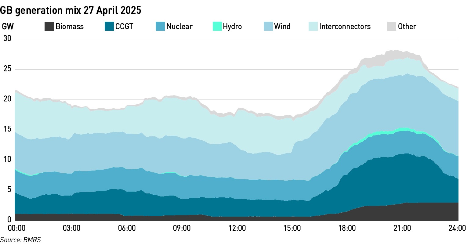
The next question is why did a grid fault cause a complete loss of the entire Iberian power grid and part of France. This is probably due to the low inertia operation of the Spanish and Portuguese power grids which have large amounts of solar generation, and also decent amounts of wind power connected. In fact, just a couple of weeks ago, REE boasted about running the Spanish grid entirely with renewable sources, with wind contributing 46% of the total output, solar PV at 27%, hydro at 23%, solar thermal at 2%, and other renewable sources including renewable waste at 2%.
However, even with the hydro, that was pretty low inertia operation. There had been warnings earlier this year when the Spanish competition authority published an analysis of voltage control within its annual review of network charging. In its report, the regulator pointed out that the growing integration of renewable energy and falling demand is causing high oscillations in the voltage levels that may result in blackouts. Redeia/REE also pointed out in a report last February that the planned nuclear exit would create “problems due to the excess of renewables.” There were particular concerns about low demand periods such as lunchtime (solar generation connected to distribution networks creates demand reduction on the transmission system).
Low inertia means that grid frequency changes more than it would in a high inertia context for the same fault, making it more likely that other grid equipment trips as its protection measures activate, leading to a cascading grid failure. France, with its grid that is dominated by spinning mass – nuclear and hydroelectric turbines – has very high inertia, which may explain why the blackout in France was limited to a small area and with power being quickly restored. Similarly, the August 2019 blackout in Great Britain was contained without causing a system-wide collapse, due to the higher inertia of the GB grid compared with Spain.
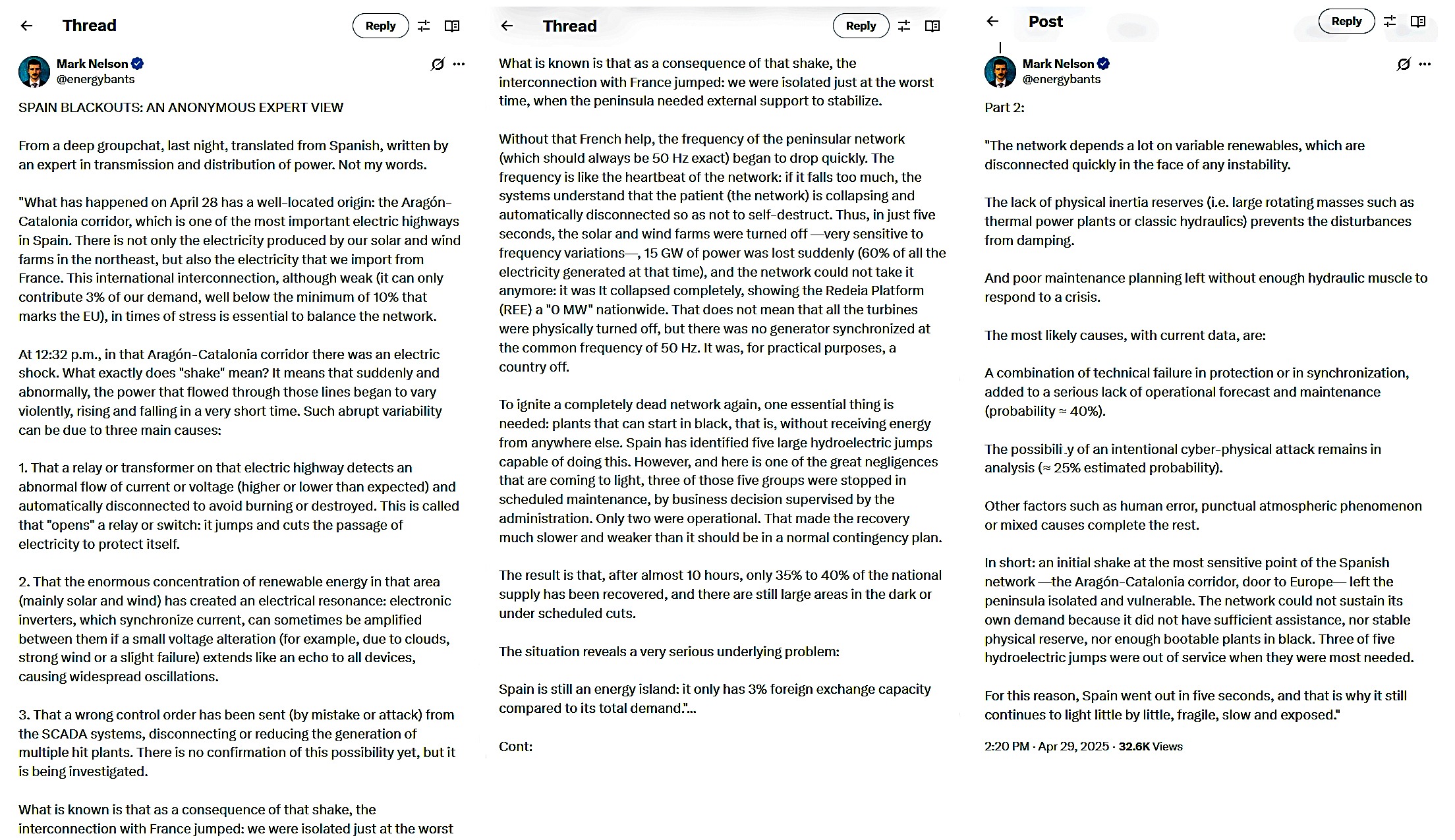
Here is a description of the Iberian blackout from an anonymous expert quoted on X (make of it what you will)
Sadly eight people lost their lives. Of the seven people who died in Spain, one was in a house fire linked to the use of candles, two were from the failure of generators powering respirators (breathing machines) and three died when the generator powering their home respirator gave off carbon monoxide. The cause of the other death is unclear. The fatality in Portugal was also linked to a respirator.
Some basics about our power grids
With apologies to my expert readers, I think it’s useful to set out the basics as many people have been asking and it’s not widely understood.
Much of the way in which the electricity system operates is driven by the physical characteristics of electricity. In the most basic sense, a generator is one magnet rotating while inside the influence of another magnet’s magnetic field. The generator consists of stationary magnets – the stator – which create a powerful magnetic field; and a rotating magnet – the rotor – which distorts and cuts through the magnetic lines of flux of the stator, generating electricity. Due to the rotation of the magnet, the direction of the current periodically reverses – this is known as alternating current and is the basic output of a generator. For this reason, generators are also known as alternators.
[videopress mUq42OJs]
This is illustrated here. A bent wire is placed between the poles of a magnet and set to rotate. As the loop of wire turns, each side will sometimes be travelling up and sometimes down – when it moves up, the current moves in one direction, and when it moves down the current moves the in the other direction. When the loop is perpendicular to the lines of magnetic flux, the current is zero, while when it is parallel to the lines of flux it is at a maximum. This is the origin of the sine waveform of the current and voltage.
An ac generator can be modified to generate direct current, creating by replacing the metal rings in the ac generator with a commutator which consists of a hollow metallic cylinder split into two halves that are insulated from each other. Two brushes are in contact with each part of the cylinder at the moment when the coil is perpendicular to the magnetic field. During the first half of the cycle, one brush touches one half of the cylinder and the other touches the other half. As the current reverses direction, the brushes swap to touch the other half of the cylinder – this reverses the external direction of the current so it is the same as in the first half of the cycle. The result is known as a dynamo.
A small detour into the history of power grids
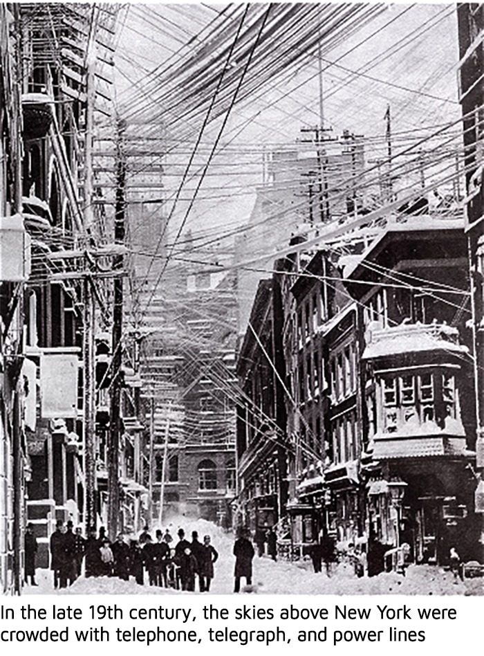
The history of how we come to use alternating current is also interesting. In September 1882, Thomas Edison opened the Pearl Street Power Station in Manhatten. This plant, fired by coal, began with six dynamos, and had an initial load of 400 lamps at 82 customers. By 1884 it was serving 508 customers with 10,164 lamps. This was also the world’s first co-generation plant, combining the provision of heating as well as power with the waste steam being piped to nearby buildings.
 Edison favoured direct current because he wanted to power electric motors as well as lights, and at the time there were no good ac motors available. However, direct current was limited because it could not be transported over long distances because too much of the energy would be lost through the wires as heat. This meant that power stations had to be located close to consumers. Alternating current on the other hand can be transported over longer distances since the voltage could be increased to a level that reduced the heating effect through the use of transformers: a “step-up” transformer increases the voltage of the electricity at the power station, and a “step-down” transformer reduces it again for distribution into homes and businesses.
In 1883 Nikola Tesla invented the first transformer, known as the “Tesla coil”. The following year, Tesla went on to invent the first electric alternator for the production of alternating current. In 1887 he patented a complete electrical system, including a generator, transformers, a transmission system, a motor for use in appliances, and lights. The scheme caused a sensation and the patents were bought by George Westinghouse.
What followed has come to be known as the War or Battle of the Currents. On the one side were Tesla and Westinghouse and on the other, Edison. The stakes were high, with the opportunity to secure the rights to electrify American cities and earn potentially huge patent royalties.
The use of ac spread rapidly, leading Edison to begin a mis-information campaign against the technology. He claimed that the high voltages used to transport alternating current were hazardous, and that the design was inferior to, and infringed on the patents behind, his direct current system. The spring of 1888 saw a media outcry over fatalities caused by pole-mounted high-voltage ac lines, attributed to the greed and callousness of the arc lighting companies that used them.
Harold P. Brown, a New York electrical engineer, claimed that alternating current was more dangerous than direct current and tried to prove this by publicly killing animals with both currents, with technical assistance from Edison. They also contracted with Westinghouse’s main ac rival, the Thomson-Houston Electric Company, to make sure the first electric chair was powered by a Westinghouse ac generator. The dirty tricks continued until the World Fair in Chicago in 1893, which was lit with an ac system and the competition between the two was effectively over. Modern electricity systems are almost all run on alternating current.
Impact of the energy transition on power grids
The energy transition has seen a major deployment of intermittent renewable generation across the world. In general, wind and solar energy is converted into direct current…although wind turbines rotate, they do not do so at a constant rate, so are unable to generate ac electricity with a stable waveform without the use of power electronics. Clearly there are no rotational elements to solar power.
In the developed world, electricity grids and all the connected infrastructure from machinery in heavy industry to the devices in our homes, are all built on the fundamental principle that the power delivered to the socket has a consistent, predictable set of characteristics. Those characteristics may differ slightly from country to country – hence the need to adaptors when using devices in another country – but the fundamental concept is the same: alternating current at either 50 Hz or 60 Hz (depending on the country) with that frequency being delivered within a very narrow tolerance band. Outside that band, equipment can fail since it is designed to operate within a narrow frequency range.
[videopress x1XIBzOU]
Not only do intermittent renewables not deliver stable ac current, they also tend to be “distributed”, particularly in the case of solar. This means instead of grids based around large units of generation connected to high voltage networks we have many smaller generation sources connected to distribution networks, and even “behind-the-meter” ie not technically on the grid at all.
This presents both physical and economic challenges. Physical challenges relate to how the stable electricity expected by end users can be maintained when the means of generation no longer supports that to the same degree, and economic since the growth in self-generation challenges the economic assumptions behind the way in which networks are built and paid for.
Grid operators are having to develop new ways of managing their networks, creating new markets for ancillary services such as fast and dynamic frequency response, reserve and reactive power products, short circuit levels and inertia support. New technologies such as chemical batteries are being used for some of these services, and old technologies such as synchronous condensers are being used in new ways to support changing grid needs.
What is inertia and why is it important?
Generators convert the kinetic energy of the spinning turbines into electrical energy. The principle of conservation of energy governs the relationship between system power and the kinetic energy of the rotors – if there is insufficient supply to meet demand, the rotors will slow down and system frequency will fall, and vice versa. A sudden loss of generation or surge in demand can lead to a rapid change in frequency, which can damage equipment connected to the grid:
- Large frequency drops can damage transformers and induction motors due to the high magnetising currents required for maintaining flux. These devices are widely used in electricity transmission and distribution networks as well as in consumer appliances, so avoiding large frequency deviations is important to avoid damaging both network infrastructure and end-user devices
- Turbine blades are designed to operate in a narrow band of frequencies to avoid mechanical vibrations of blades at their natural frequencies – operation outside this frequency range can damage the turbine
- Drops in frequency cause the air flow in generators and turbines to fall, thus reducing cooling, while generator control systems increase their input power to maintain the generation and demand balance, which may result in an increase of the internal temperature of the turbine and generator windings – as the internal temperature increases, the protection devices cause the generator to disconnect from the grid, increasing the imbalance between demand and generation
- Increases in generator power output can also overload transmission lines, causing them to trip
For these reasons, system operators are required to maintain frequency within narrow limits and, if frequency deviates, to restore it to normal levels within a specified time period. In all global electricity grids, these requirements are part of the system operator’s license conditions.
The level of this challenge is illustrated by this chart which shows demand through the day on two days separated by 6 months. As you can see, winter demand is, as expected, higher than in summer when less heating and lighting is needed.
.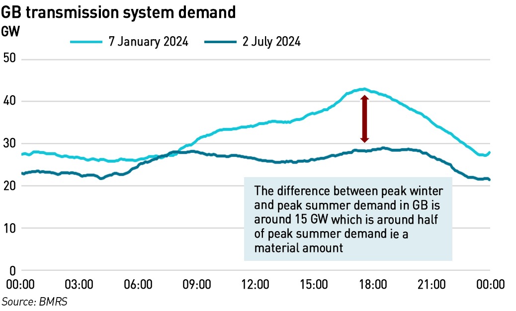
Demand also varies through the day with a strong peak in the evening as the nation comes home from work and cooks dinner, and low demand at night when people are sleeping.
Many countries around the world are transitioning their electricity systems from ones dominated by conventional fossil fuel and nuclear generation, where the large, heavy turbines described above rotate in synchronicity to generate electricity at the required frequency, to systems with higher proportions of intermittent renewable generation.
In a conventional electricity system, these large heavy turbines do not just generate electricity at the desired frequency, they inhibit changes in grid frequency through their physical characteristics: large, heavy objects are difficult to move, and resist changes to their movement. Energy is delivered to the turbine causing it to rotate at a constant speed – more energy is required to change that speed if the input energy remains constant. In this way, these turbines resist changes to grid frequency caused by fluctuations in supply and demand, a property which is known as “inertia”.
The growth in intermittent renewable generation disrupts system frequency in two ways:
- Intermittent renewable generation delivers an output that is highly variable in time. Wind speeds are rarely constant, changing in both intensity and direction by the second, and similarly cloud patterns can create significant, instantaneous variations in solar output. Changes in either generation or demand can lead to changes in grid frequency, so highly variable generation patterns make maintaining a stable grid frequency more difficult
- Intermittent renewable generation is increasingly displacing conventional generation in the generation mix, reducing the amount of heavy, rotating turbines on the grid and therefore the amount of inertia they provide
“Operating the system with low inertia will continue to represent a key operational challenge into the future and we will need to ensure we improve our understanding of the challenges this will bring,”
– National Grid ESO
Taken together, these effects are making it increasingly difficult for system operators to maintain grid frequency, and in some regions such as South Australia, solar power is curtailed in order that gas generators can run, purely so that they can provide electricity at the correct frequency and deliver inertia to the grid.
No doubt Thomas Edison would feel vindicated in his support for direct current, but as replacing existing grids would be unfeasibly expensive for the most part, grid operators are looking at different types of inertia provision that can support systems with high levels of intermittent renewable generation, and there are plans to try to get inverter-based renewables such as wind and solar to create the ac waveform through so-called “grid-forming power electronics” (“GFPE”)
Can inverters cause grid voltage oscillations?
The answer to this is yes, under certain conditions, inverter-based resources (“IBR”) such as solar PV, batteries, and wind turbines can cause grid oscillations, although that is not to say this was the cause of the Iberian blackout. To understand why IBR can cause grid oscillations it’s necessary to understand what inverters actually do.
The purpose of an inverter is to convert dc electricity generated by solar panels, batteries and wind turbines (wind turbines generate alternating current, but not with constant frequency so they cannot synchronise to the grid. To get round this, the ac generated is converted to direct current and then back to ac for connection to the grid). Inverters not only convert from dc to ac, but they need to do so in a way that is compatible with the power grid. This means they must:
- Match the grid’s voltage and frequency (eg 240 V, 50 Hz in the UK)
- Synchronise phase angle and wave shape with the grid
- Inject power (active and reactive) into the grid as instructed by controls or markets
To do this, the inverter uses:
- A switching bridge (eg insulated-gate bipolar transistors (“IGBTs”) or metal-oxide-semiconductor field-effect transistors (“MOSFETs”))
- Filters (to smooth out the pulse width modulation (“PWM”) switching)
- A control system (to regulate output)
- A phase-locked loop (“PLL”) to “track” the grid voltage phase/frequency
Inverter controls assume they’re connected to a reasonably strong grid, where voltage is “stiff “(ie doesn’t sag or distort), impedance is low and inductive, and frequency is stable and easy to follow. (People often get stuck on impedance and inductance. Inductors are like capacitors in that they store energy, but in magnetic rather than electric field. Their effects are mainly seen in alternating current systems, not direct current, because inductance depends on changes in current and voltage over time. Impedance is similar to resistance but also accounts for the effects of inductance and capacitance. It represents the overall opposition to current flow in an ac grid, combining conventional resistance (as in dc circuits) with additional effects caused by the changing current in the presence of inductors and capacitors.)
Even without loads, power grids contain both resistance and impedance. Power lines don’t conduct electricity perfectly — some energy is lost as heat due to electrical resistance. Long power lines also behave like inductors because when ac current flows through a conductor, it constantly changes direction, and this changing current generates a changing magnetic field around the wire (by Ampère’s Law). This magnetic field, in turn, induces a voltage (by Faraday’s Law) that opposes the change in current. This opposition is inductive reactance, which is what inductors do. Over a longer conductor, the total magnetic field created is larger, and the effect is stronger so the wire behaves more and more like an inductor the longer it gets. Similarly, the windings in transformers create magnetic fields and are a classic source of inductance in power grids. Then there is the effect of loads such as motors which can be both inductive and contain capacitors.
Impedance causes problems for inverters in a number of ways:
- Instability in control loops: if the inverter thinks the grid is stable but it’s not, its control loop can overshoot, oscillate or lose synchronisation (PLL unlock)
- Harmonic interaction: high impedance at certain frequencies can amplify harmonics – inverters create some harmonics by design (from switching) but normally, they’re filtered out or absorbed by the grid. In a weak grid, these harmonics reflect back and build up creating resonance
- Sub-synchronous resonance: at sub-50 Hz frequencies impedance may create oscillating power flows, current/voltage instability and damage to cables, filters, or transformer windings
Returning to the question about inverters causing grid voltage oscillations these typically happen through control interactions, lack of damping, or fast-acting power electronics responding poorly to weak grid signals. The key mechanisms of such oscillations are:
- Phase-locked loop (“PLL”) instabilities: inverters need to synchronise with grid voltage and frequency via PLLs. In a weak or noisy grid, PLLs can lose lock or misinterpret disturbances, leading to unstable current injections and oscillatory feedback
- Low inertia and fast response: unlike synchronous machines, inverters don’t possess inertia, ie they don’t naturally resist changes in grid frequency. However, their response is not necessarily passive – their speed of response can sometimes amplify grid disturbances instead of smoothing them as a heavy spinning mass would
- Resonance with grid impedance: inverters interacting with certain line or transformer impedances can excite harmonic or sub-synchronous resonances particularly in weak grids. In real world power grid applications, oscillations are seen in offshore wind farms due to long cables.
- Poor coordination: If multiple inverters or parks use similar fast-reactive controls (eg droop response, virtual inertia), they may reinforce each other’s actions and create a positive feedback loop
Not only can inverters create grid voltage oscillations they can also amplify existing oscillations. This is actually more common than them creating oscillations in the first place. If a grid is already oscillating due to a disturbance such as a sudden large generator or interconnector trip, inverters can:
- Misinterpret voltage/frequency swings, causing over- or under-reaction
- Inject reactive power too aggressively (or with delay), adding energy to the oscillation rather than damping it
- Enter anti-islanding or fault ride-through modes erratically — some will stay connected, others may trip too fast, worsening the imbalance
Modern grid-forming inverters are designed to damp such oscillations, but almost all inverters currently deployed in western power grids are grid-following and were not designed to operate under stressed or low-inertia conditions.
There is precedent for inverters causing blackouts. In the 2016 South Australia blackout, wind farm inverters misread a sequence of faults and collectively disconnected, precipitating grid collapse. According to the official report by AEMO:
“On Wednesday 28 September 2016, tornadoes with wind speeds in the range of 190–260 km/h occurred in areas of South Australia. Two tornadoes almost simultaneously damaged a single circuit 275 kilovolt (kV) transmission line and a double circuit 275 kV transmission line, some 170 km apart. The damage to these three transmission lines caused them to trip, and a sequence of faults in quick succession resulted in six voltage dips on the SA grid over a two-minute period at around 4.16 pm.
As the number of faults on the transmission network grew, nine wind farms in the mid-north of SA exhibited a sustained reduction in power as a protection feature activated. For eight of these wind farms, the protection settings of their wind turbines allowed them to withstand a pre-set number of voltage dips within a two-minute period. Activation of this protection feature resulted in a significant sustained power reduction for these wind farms. A sustained generation reduction of 456 megawatts (MW) occurred over a period of less than seven seconds.
The reduction in wind farm output caused a significant increase in imported power flowing through the Heywood Interconnector. Approximately 700 milliseconds (ms) after the reduction of output from the last of the wind farms, the flow on the Victoria–SA Heywood Interconnector reached such a level that it activated a special protection scheme that tripped the interconnector offline.
The SA power system then became separated (“islanded”) from the rest of the NEM. Without any substantial load shedding following the system separation, the remaining generation was much less than the connected load and unable to maintain the islanded system frequency. As a result, all supply to the SA region was lost at 4.18 pm (the Black System). AEMO’s analysis shows that following system separation, frequency collapse and the consequent Black System was inevitable.”
While the initial grid fault in Spain was probably not inverter-related in this case (although this remains a possibility), the low inertia operation of the grid is likely to have been the reason the fault was not contained until it reached France, and there was a full blackout on the Iberian peninsula.
Are GFPE the answer?
With its large amounts of solar power, the Australian system operator, AEMO is at the forefront of the work on grid-forming power electronics. Its trials have been progressing, albeit with some challenges. In January 2024, AEMO released a “Core Requirements Test Framework” for grid-forming inverters, building upon their 2023 voluntary specifications. These documents outline the desired capabilities of grid-forming inverters, such as voltage source behaviour, inertial response, and fault ride-through capabilities.
While these specifications provide a foundation, the practical implementation has revealed complexities. For instance, achieving the necessary energy headroom for inertial response can be challenging, especially for offshore wind power plants where curtailing output to provide headroom may not be economically viable. Additionally, ensuring interoperability among devices from different manufacturers and adapting to varying grid conditions require further research and development.
More specifically, GFPE face the following challenges:
- Technical risk: GFPEs need to mimic inertial and voltage-source behaviour in real time — this requires fast, stable, robust control, which is still being refined
- Commercial hesitation: developers and investors are cautious because there are few clear grid codes or performance standards and regulatory frameworks are still evolving. Energy headroom requirements reduce revenue potential
- Interoperability concerns: GFPE units from different vendors need to co-operate without destabilising the grid which, is not straightforward given issues around commercial confidentiality
- Operator caution: TSOs are reluctant to rely on GFPEs until there are more data from field-testing
AEMO is working on these issues with industry stakeholders – its efforts are focusing on enhancing testing methodologies, improving control strategies, and developing standards to facilitate the integration of grid-forming inverters into the Australian power grid (NEM). It wants up to 30–50% of new inverters to be grid-forming by 2030.
Notable projects GFPE projects in Australia include:
- Hornsdale Power Reserve (South Australia): this 150 MW /194 MWh battery system, co-located with the Hornsdale Wind Farm, has been upgraded to provide grid-forming capabilities. It delivers synthetic inertia and fast frequency response, enhancing grid stability in a region with significant renewable energy resources
- Dalrymple ESCRI Battery (South Australia): a 30 MW/8 MWh battery that supports a 100% renewable microgrid on the Yorke Peninsula. It enables the region to operate independently during grid disturbances, showcasing the practical application of GFPE in enhancing energy resilience
- Victorian Big Battery (Victoria): with a capacity of 300 MW/450 MWh, this facility has been tested for grid-forming capabilities, contributing to system strength and reliability in Victoria’s energy network
Beyond Australia, GFPE technologies are being implemented in various Western power grids:
- United States: grid-forming inverters are being integrated into projects like the Los Angeles Department of Water and Power’s initiatives to enhance grid stability amidst increasing renewable energy adoption
- Europe: countries such as Germany and Great Britain are exploring GFPE to support their energy transition goals, with pilot projects demonstrating the technology’s potential in maintaining grid reliability. In Britain, NESO has used its Pathfinder projects to explore commercial procurement of inertia, and recently connected a grid forming battery in Scotland
- Middle East: GFPE is being considered in regions aiming to diversify their energy mix and incorporate more renewable sources, with pilot projects assessing their feasibility and benefits
The deployment of grid-forming power electronics in Spain remains limited, despite the large amounts of inverter-based renewables, particularly solar power, that has connected to the Spanish power grid.
In summary, no western country currently uses grid-forming power electronics outside limited trial scenarios, and it may be several years before widespread deployment is seen.
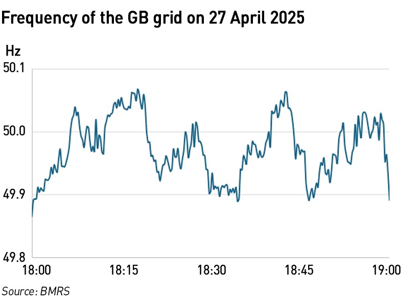
Weird voltage behaviours on the GB grid the day before the Iberian blackout
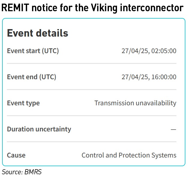
In the early hours of 27 April 2025, the day before the Iberian blackout, the GB power system experienced unusual voltage disturbances, triggering protective trips at the Keadby 2 CCGT and the Viking interconnector with Denmark. The incident occurred just after 3:00 am. The Viking REMIT notice specified “Control and Protection Systems” as the reason for its unplanned trip. Keadby had been returning from a longer outage.
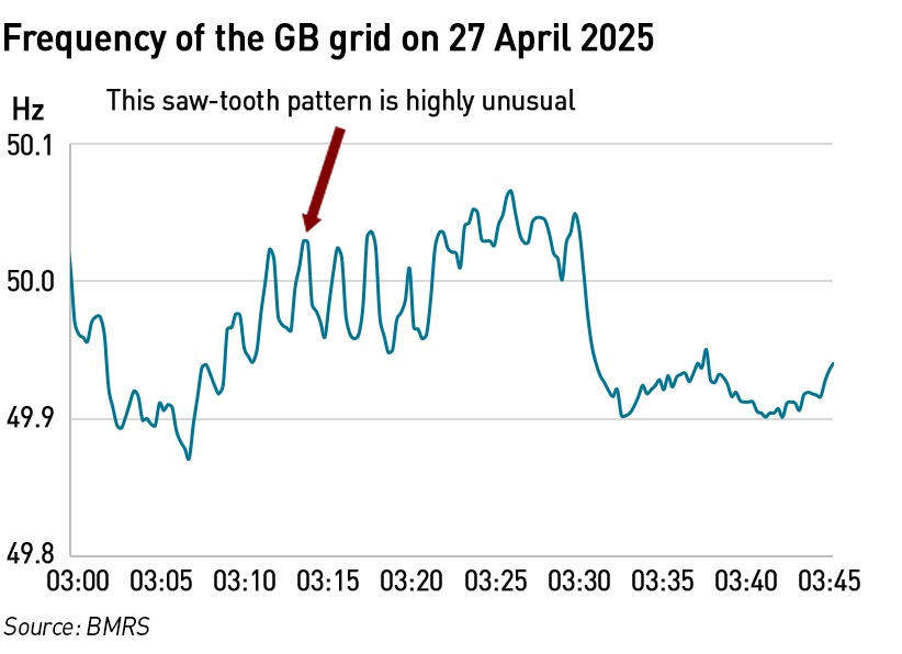
Clear oscillations in frequency are visible shortly after 3am between ~49.92 Hz and ~50.05 Hz. The oscillation frequency appears to be in the 100–200 second range (0.005–0.01 Hz), suggestive of inter-area or mode instability. These are not normal load-following frequency variations, but a sign of poor damping of an active oscillatory mode — often linked to:
- HVDC control interactions (e.g. interconnectors)
- Generator control system interactions
- Weak system areas connected via long corridors
There is then a drop to 49.85 Hz at around 3:30am which suggests a large, fast disconnection (like a power station or interconnector tripping).
The oscillations before 03:30 imply a system already under stress or poorly damped. The event at 03:30 appears to have snapped the system into a new state, possibly triggering protection schemes or tripping logic due to instability.
Inertia at the time was not unusually low, which suggests this was likely a control-mode instability, not raw RoCoF (Rate of Change of Frequency)-driven collapse.
According to NESO, these events were resolved swiftly and did not lead to consumer disconnections – which is not surprising given they occurred in the middle of the night.
While the grid was operationally intact it was dynamically unstable, which suggests a need to review the tuning and coordination of grid-following assets (eg interconnectors, inverters), mode damping contributions from synchronous plant, or the effectiveness of frequency stability services (like dynamic containment) under oscillatory conditions.
Later in the day, around 6pm, further unusual oscillations were observed. There were notable frequency spikes and sharp reversals just before and after 18:00, with several steep drops followed by rapid rebounds.
This pattern suggests sudden generation or interconnector disconnection or possible control loop interaction for example, response overshooting from frequency response providers. As there were no reported large generator or interconnector trips at the time, more likely causes are:
.
- Control or dispatch error: a sudden imbalance caused by poor dispatch timing (eg under-delivery of frequency response or over/under ramping of flexible assets) which could involve distribution-connected assets, which aren’t captured in REMIT
- Embedded generation behaviour: a sharp solar PV cutout (eg due to irradiance loss or inverter group behaviour) might affect net load shape without showing up in REMIT, which could explain a short, steep imbalance without a formal “trip”
- Frequency response overshoot or interaction: dynamic containment or low-frequency response from storage could have overreacted, causing the kind of spike–rebound signature seen at around 6pm
.
The GB grid was not running with low inertia on 27 April, so these oscillations are unusual. Fortunately, the high inertia meant the impact of the oscillations was limited and there was no loss of load, but on a low inertia day, the outcome could have been different. There is no suggestion that these oscillations were related to the Iberian blackout.
.
While we may not know the true cause of the Iberian blackout for some time, we have a reasonable idea about why it was so widespread. Full system-wide outages are rare, as are the black starts that follow, but with the growing reliance on inverter-based renewables, electricity grids are becoming less stable. No doubt system operators around the world will be reviewing their approach to maintaining inertia in the aftermath of this incident.
Blackouts kill. We should not risk people’s lives in the quest for net zero.
How many politicians are aware of the complexities of solar and wind on a grid, or even how varied it’s output is?
It seems clear to me that we should be re thinking the whole idea instead of trying to find solutions to a problem that we should not have in the first place.
The idea that we can power a country with variable and uncontrolled output from wind and solar should have made it a non starter from the inception.
It’s funny how many people were calling me to learn about inertia last week!
As usual, a very clear explanation of why this Government’s rush to net zero is dangerous and especially so if they don’t get new nuclear power on the grid before they commission more wind turbines and solar panels.
A very informative article which should help anyone to better understand current grid issues and future grid developments .
Turning a simplex synchronous electromechanical based system into a duplex electromechanical-phygital synchronous-inverter based system can’t be straightforward .
Load tiering of household appliances seems a natural evolution. Does this imply a market for smart appliances or more sophisticated household wiring?
“We should not risk people’s lives in the quest for net zero” is an interesting closing comment, especially since the impacts of global warming are often estimated as order(s) of magnitude more significant than covid. Hence getting to net zero is surely there to remove/reduce the risks of larger global problems in the future?
Feel like a set of constructive solutions to increase system inertia are needed quickly, but its certainly not as simple as ‘stop net zero’ – surely?
Actually no, I don’t agree. Humans are not responsible for all climate change – climate was changing before humans existed – so some deaths from climate change cannot be prevented. However we absolutely can and should prevent avoidable deaths arising from bad policies
Certainly the climate can change naturally, in addition to from human activities, but you did say that some is caused by humans so you would see some value in minimising that effect? (just because some deaths may happen naturally, it doesn’t seem logical to do nothing for the others).
Even the lowest estimate of (commonly accepted by scientific population) studies, has 74% of climate change caused by humans, and the average/mode appears to be in the very high 90’s%, which would definitely imply as humans we have a very significant part to play. The consequences of Covid were pretty extreme, and affected most of the planet, so if climate change is order(s) of magnitude more dangerous then some sacrifice/adaption seems important?
The UK is responsible for 0.8% of global emissions. The sacrifice we are making is of no use when China, Russia, Iran and many others turn our expensive energy policies into weapons to destroy our economy and democracy. China in particular is burning more coal now than ever before and in 2024 burnt more coal and produced more emissions than had been saved by closing coal power stations in the west. China manufactures the renewable power technologies we buy from them by burning coal. We have to be realistic, the fact is that global energy production, use and emissions have grown substantially since COP started. The only way to reduce emissions is to develop new flexible and energy dense fuel technologies i.e. nuclear power, Our ‘sacrifice’ and policies to reduce our use of energy will never be enough to make a difference on the global stage.
I’m afraid that’s just like saying there’s no point saving money as I’ll never be the richest person in the world. Everybody has the power to do something that collectively becomes significant.
China installed more solar last year than the rest of the world combined last year, installed more hydro and wind in 12 months than the UK’s total capacity, and it’s emissions have already peaked. They are the ones innovating with low carbon tech such as trains that go faster than planes, so really they will be the future unless we act now!
To predict that China’s emissions have peaked is crystal ball gazing. But what China has done is develop a prototype thorium fuel reactor, using IP from the US and if that works then this molten salt tech will indeed be a game-changer and will make all our solar panels and wind turbines look like a £200 billion waste of taxpayers money.
‘Estimated’ doing a lot of work there, what are certainly at least an order of magnitude different are deaths from cold and heat (even in ‘hot’ countries). What have certainly fallen dramatically are deaths from natural disasters mainly due to the availability of affordable energy and greater wealth. Denying affordable energy to poor countries for cooking, light and water supply and treatment is disgraceful.
Affordable energy is a different topic to this IMHO and the objective is clearly not to deny people energy, its around stability of supply from the post, but in most cases renewable energy will work out cheaper over its lifetime – even if there is no carbon tax. Energy independence is also far greater with solar as in poor countries they are no longer reliant on a supply of fuel from “somewhere else”.
On the deaths point, if the deaths are increasing by at least an order of magniture as you say then surely this is the next problem to solve, if we’ve already made enough progress on natural disasters (which will increase from climate change too).
Great analysis, Kathryn. Really sharp. Thanks for writing it.
It’s clear that the Gran Apagon is now a political football in Spain, with the time horizon for public revelation of official explanations being pushed further and further back (now six months at least) and the involvement of more and more politicians rather than grid specialists in the process. Sanchez is deeply wedded to a renewables based future, and has gone out of his way to attack nuclear power – which he had been trying to close down anyway – as being “useless” following the apagon: he has vowed to continue to proceed with nuclear closures from 2027. That more nuclear might have prevented it altogether had more nuclear been running (there were three stations shut for refuelling/maintenance or regulatory reasons) is an idea not to be entertained. However, there was also minimal CCGT in operation as well, leaving the bulk of the inertia provision to the remaining nuclear, some hydro, and pumping for pumped storage.
Under the low frequency demand protocols, pumped storage pumping is the first demand to be disconnected at below 49.1Hz. The effect would have been to remove an important chunk of inertia along with the demand. Further automated demand disconnection occurs at frequencies down to 48Hz supposedly now in 6 steps down to 50% of demand if Spain has implemented the ENTSO-E protocol that they were supposed to by 2022 (I can’t find confirmation that they did so). Main generators are supposed to ride through down to 47.5Hz. The fact they all failed suggests that the rate of change of frequency was so dramatic that even with the demand disconnection there was no preventing the cascading trip of generation. The lack of any kind of frequency trace being made public is further evidence of the degree of political cover-up that is in train. Frequency traces can be very diagnostic of events.
There are reports of regular incidents with power surges and wild voltage oscillations on the Spanish grid in recent months, making it seem that this was an accident waiting to happen. This article, supposedly based on a discussion with a Red Electrica insider, offers a useful perspective:
https://www.articulo14.es/sociedad/un-experto-en-red-electrica-revela-las-claves-del-apagon-en-espana-y-portugal-20250429.html
He starts by noting the low level of inertia on the grid as a key enabler of the blackout. He continues by noting that conventional generation is fitted with “power oscillation damping”. He goes on to say a more plausible explanation could be related to a more complex phenomenon: the interaction between generator controllers and the limited presence of oscillation damping (POD) systems in certain areas of the grid. Under certain conditions, the electrical impedance between several generators can cause their controllers to conflict , generating what is known as power oscillations .
These oscillations occur when the generators are not perfectly synchronized: one increases its input while the other decreases it, and vice versa. If this dynamic aligns with a resonant frequency, it can cause a progressive amplification of the oscillations that ultimately compromises the stability of the system. “This is a phenomenon that is difficult to anticipate and simulate , but one that REE is actively studying through advanced models,” he asserted.
This article was put together soon after the apagon – the worst in Spainish history – occurred, and before the politicians weighed in:
https://www.eleconomista.es/energia/noticias/13337393/04/25/espana-sufre-el-peor-apagon-de-su-historia.html
It mentions the wild voltage fluctuations on the grid, including the previous week when Adif suffered a voltage control problem that caused several trains to stop and left the Madrid-Chamartún station inoperative for several hours. The National Markets and Competition Commission had published in January an analysis that pointed out that lower demand led to less need for active power on the grid creating a surplus of reactive power that leads to overvoltages. It mentions that these are handled by circuit breakers tripping out transmission lines, alongside switching in reactances to absorb the reactive power surpluses, but this method of handling the surges is running out of room, and there is often a need to increase conventional generation (unstated: and curtail renewables to match). In a nice analogy for reactive power, it is described as the foam on the top of a glass of beer, when we really want just the liquid to drink.
Before he was unceremoniously silenced by the government, Edmundo Prieto, the Director for Operations at Red Electrica spilled some beans: he mentioned that two transmission lines tripped out 1.5 seconds apart (later data revealed it was 1.3 seconds) in the southwest of the country, and admitted that you could anticipate that since the area is dominated by solar, solar was responsible. He claimed that the first loss was survivable, but the second led to an uncontrollable trip of the whole grid.
https://www.europapress.es/economia/energia-00341/noticia-restablecido-9995-demanda-electrica-700-horas-red-electrica-20250429115326.html
In essence, the idea is that overvoltage from oversupply in the local grid area leads to a transmission line tripping out. This then results in reduced power delivery, and an attempt by the grid to automatically reconfigure to transmit the produced power, which leads to more overvoltage and local overfrequency that will cause the solar to trip out, but not before the second transmission line trips out through overload. Meanwhile the rest of the grid loses a substantial supply (if you look at the grid configuration you will find that there is remarkably little generation around Madrid: it draws supply from around the country. Pan around and zoom in here to see the gird and its inputs and connections https://openinframap.org/#6/39.619/-3.467/L,P,S ) with the result that there is an acute shortage of power in the rest of the country, and a rapid collapse in frequency as a result, with little resistance from the limited inertia.
All this suggests that the problems did not start at the French end of the country, although it would all have tripped out soon enough. Perhaps the idea that the North was to blame comes from the previous incident in 2021 that resulted in separation from the European grid. There is a very comprehensive ENSTO-E report here:
https://eepublicdownloads.azureedge.net/clean-documents/Publications/2022/entso-e_CESysSep_210724_02_Final_Report_220325.pdf
A reading of that report might suggest that the 868MW of exports to France on 28th April ahead of the event were probably not all that instrumental in the main Spanish event. We can I suppose expect that eventually ENTSO-E will get ot provide hopefully at least a comprehensive report on the incident. Meantime, the Spanish government were further embarrassed by a large power outage near Las Palmas – this due to an aged substation tripping out (see Heathrow!). That only seem to have hardened the government against any rapid recognition of the truth.
Thanks for clarifying the confusing graph under “What Happened”, namely that the post-fault half is phantom data, not real data.
The precise cause of the outage may not be important as the grid ought to be able to withstand almost any sudden perturbation (barring a catastrophic event). I’m intrigued by the possibility that it may have been caused by a weak spot in the earth’s currently-waning magnetic field which allowed a solar wind plasma penetration breakthrough type of event to occur despite low solar activity at the time. If so, it is worrying that a repeat occurrence might easily happen. I picked this up via a chance link to this SpaceWeatherNews YouTube: https://www.youtube.com/live/TYuPQ2NbkwA.
A deep-dive into understanding such catastrophist space weather events would take time and effort. Even the linked clip is 90 minutes long although the main points seem to be covered in the first ten or so minutes. Short of taking the deep dive (which I haven’t), it may be worth keeping an eye open for any further news on this, although it’s unlikely to reported by the MSM.
Almost six years I questioned then Business Secretary Andrea Leadsom on whether the UK was already close to the upper limit of non-synchronous wind and solar [and now interconnectors] penetration following the August 2019 outage. It led to an involved to and fro with her BEIS minions, all documented here: https://edmhdotme.wpcomstaging.com/the-case-against-net-zero-co2-emissions-2/.
There are all sorts of risks we face. Some will be difficult to manage like the effect of solar flares etc, but some should be perfectly manageable like regular grid faults. It needs grids to be properly maintained and properly managed with adequate levels of inertia and reserve
More research on versual inertia is needed especially for grids with high share of renewable energy sources.
I have read : “National Grid said that its current policy was to ensure that system inertia was always above 140 GJ. “
If it is correct that system inertia is the kinetic energy from the mass of rotating thermal generating plant and that the kinetic energy available to prevent grid instability is limited by the frequency limits does anyone know what generating capacity is necessary to be online to be able to supply this 140 GJ?
Wow thats a monster of blog very comprehensive.
ENTSO has published a high level overview earlier
https://www.entsoe.eu/news/2025/05/09/entso-e-expert-panel-initiates-the-investigation-into-the-causes-of-iberian-blackout/
This is there high level sequence of events
Before the incident, the international exchange programs of Spain were 1,000 MW to France, 2,000 MW to Portugal and 800 MW to Morocco, all in the exporting direction.
Data so far, have yielded the following sequence of events during the incident:
1.Starting at 12:32:57 CET and within 20 seconds afterwards, presumably a series of different generation trips were registered in the south of Spain, accounting to an initially estimated total of 2200 MW. No generation trips were observed in Portugal and France. As a result of these events the frequency decreased and a voltage increase is observed in Spain and Portugal.
2.Between12:33:18 and 12:33:21 CET, the frequency of the Iberian Peninsula power system continued decreasing and reached 48,0 Hz. The automatic load shedding defence plans of Spain and Portugal were activated.
3.At 12:33:21 CET, the AC overhead lines between France and Spain were disconnected by protection devices against loss of synchronism.
4.At 12:33:24 CET, the Iberian electricity system collapsed completely and the HVDC lines between France and Spain stopped transmitting power
They’ve assembled a panel to lead the investigation lets hope REN cooperate and release the vast amounts of data that would have been acquired through telemetry and intelligent protection relays.
Thanks for this. I’d like to see ENTSOE require all European TSOs to publish near-real time frequency data for a start.
Re lessons not learnt, here’s a recent statement by Ernesto Huber, the then-coordinator of Chile’s national grid regarding February’s Apagón:
(translated and misquote-corrected)
“everything indicates that in the not-too-distant future, generation will be 100% renewable, and to achieve this state, we must be certain that situations like this will not be repeated in the future, since it ultimately puts the security and reliability of the system at risk.”
As elsewhere, this is what comes out when a politically-driven green narrative attempts to override reality.
Source here:
https://www.latercera.com/pulso/noticia/apagon-coordinador-detecto-centrales-convencionales-renovables-y-pmgd-que-se-desconectaron-antes-de-tiempo-y-propagaron-la-falla/
Hello Kathryn, thank you for this tour d’horizon of the grid and its current stability issues. I approach the matter from the electrical machine perspective and wish to make the following points:-
The large inertia of the synchronous generator and its turbine is, at its simplest, entirely passive in its fault ride-through capability. The larger the inertia, the smaller the frequency disturbance. In addition, the inertia does NOT rely upon a command-and-control system to detect and then respond correctly to grid disturbances.
However, the synchronous machine offers additional benefits which aid in providing grid stability both during the fault and in the post-fault return to steady-state operation. Damper windings on the rotor surface provide passive damping of post-fault rotor ‘hunting’ oscillations.
The synchronous generator and its turbine also incorporate active measures for responding to grid disturbances. For example, large and rapid changes to the DC field excitation current can assist with strengthening the net magnetic field within the machine thereby reducing the tendency to pole slip. And once steady-state stability has returned, the field current can be set at a level suited to the new (i.e. post-fault) grid requirements for real power (measured in watts (W)) and reactive power (measured in volt-amps reactive (VARs)). Expressed differently, the generator’s field current controls the power factor at the generator terminals.
In short, following decades of development the wound-field synchronous turbine generator provides many well understood and well mastered means, both active and passive, of providing grid stability, not the least of which is its large spinning kinetic energy (commonly known as “inertia”). Therefore, and because grids are always under threat from all sorts of faults (e.g. lightning strikes), I recommend their use (and indeed their reintroduction!) to all grid developers who wish to provide and maintain intrinsic robustness of their system, especially in those grids where, as Kathryn’s article makes plain, the immature technology of grid-forming power electronics (GFPE) is being “perfected”.
Regards, John Cullen.
Perhaps the greatest advantage that wound-field synchronous machines have over power electronics is that they are designed to produce an almost perfectly smooth sinusoidal waveform of fundamental frequency (50 or 60 Hz) with very low harmonic content during steady-state operation. By contrast power electronics will typically approximate the pure sine wave with a stepped waveshape, although the number of steps from maximum to minimum voltage can be quite large: Weedy [Ref. 1] suggests that up to 300 steps had been achieved over a decade ago in multi-level converters for HVDC applications.
Reference 1. B.M. Weedy et al., ‘Electric Power Systems’, 5th ed., Wiley, 2012, especially page 350.
Regards, John Cullen.
Terrific article, just right for those of us who have a technical background, but aren’t power engineers.
Further to your description of the South Australia blackout (I live there!) … the report you quote from has a table (Table 11) of similar events (loss of generation) which didn’t result in a black system despite losing more
generation. The difference between the 3 prior events with no blackout and the blackout event was a significant inertia reduction and the incredible speed at which our (main) interconnector dropped. To mitigate the problem they subsequently installed 4 synchronous condensers to boost inertia. At the time, all the relevant politicians swore blind that the blackout had nothing to do with renewables. By the time the report appeared, the blackout was ancient history and the explanation shifted to “inappropriate settings on wind farms”.
The first frequency/RoCoF trace I’ve seen, published at Spanish Wikipedia which has been assembling a good article on some of gge recent history of instability that preceded the apagon.
https://upload.wikimedia.org/wikipedia/commons/8/80/2025-04-28_Blackout_in_ES%2BPT_%E2%80%93_frequency_measurement.png
RoCoF at 4Hz/sec would knock out most generators.
The Wikipedia article is here for those who read Spanish or can plug in to a translator.
https://es.m.wikipedia.org/wiki/Apag%C3%B3n_en_la_pen%C3%ADnsula_ib%C3%A9rica_de_2025
Given that:-
(i) wound-field synchronous generators and the AC grid have developed together over many decades,
(ii) wound-field synchronous generators have many useful properties (as described in my earlier posts above) that, when correctly employed, assist in fault recovery on the AC grid.
Thus, in a sense, the wound-field synchronous generator can be viewed as part of an AC system’s protection systems (although I have not seen it so described previously).
In light of the above, the introduction of essentially DC systems (such as wind and solar generation) to an AC network is, at first sight, equivalent to making the grid deficient in protection equipment.
As events in Iberia have recently demonstrated, many countries are so very dependent upon the reliability of their AC electrical grid. Hence grid reliability and integrity must not be heedlessly compromised. This suggests that the introduction of unconventional (e.g. DC) generator resources to the grid should not be undertaken so rapidly that, as estimated by sound engineering (rather than political) judgement, grid stability is threatened.
Where grid instability is most likely to occur (e.g. in a grid which is largely dependent at any instant upon unconventional resources) there must be long-term AC resources immediately available to assist with blackstart recovery. The short- to medium-term resources of pumped storage schemes (with their finite energy resources) may not be sufficient for rapid blackstart recovery.
The above observations have serious consequences for an islanded AC grid such as the UK’s with its several HVDC links to neighbouring grids and its regular habit of importing over 20% of its electricity requirement over these links. National security has, I suspect, been very greatly compromised by allowing such a situation to arise, albeit over several decades. Urgent remedial action is probably in order. Regards, John C.
This post includes frequency traces in the period running up to the blackout for several locations around Europe.
https://gridradar.net/en/blog/post/blackout-iberian-peninsula
The oscillations in frequency mentioned in various news reports can be clearly seen. These kind of artifacts are almost certainly the result of unexpected resonances between inverter sources upsetting their PLL circuits. The fact that echoes of these are seen as far away as Rgia, Latvia means that ENTSO-E – not just Red Electrica – has serious issues to address.
What I see, as a failed (BEng, electrical, never finished…) is emergent behavior. Given a large number of connected generation devices , differing makes and models of said gear, normal grid operations such as changing transmission routes and hence line length and impedance, or centrally switching in reactive power correction, it is frankly little wonder that unpredictable, emergent behaviors – er- Emerge.
A topic for another article/tour-de-force?
I was having a view of this ABB website with a pony motor connected to flywheel connected to synchronous condenser. https://smartsocieties.abb.com/home/smart_city_h/wind/wind_condenser . I asked a question about the pony motor on Jack Devanney’s website, I’ll also place it here, as I would really like to obtain a better understanding of these systems. “I assume they (pony motor) run on gasoline? I assume this is inconsequential? Doesn’t gasoline go stale, so if this is run occasionally, maybe gasoline needs to be discarded? Maybe at some point if there is more and more of these systems that need to be deployed with increasing wind and solar deployments, this may not be so inconsequential?”
Kathryn a gentlemen named Wayne Porter was good enough to post a link to your article in the comments to my piece. Thought I would share, https://open.substack.com/pub/kilovar1959/p/the-iberian-blackout-on-that-day?r=23kggy&utm_campaign=post&utm_medium=web&showWelcomeOnShare=false
This comment came up on a sub-forum of a motoring website which discusses power generation in the UK, concerning the topical issue of inertia, etc:
“Condi said:
I assumed they were limited by the inertia requirements which were lowered last year. Not sure if they were operating at the lowest requirement last year or not, but I’ve not seen anything change between then and now, so if the plan is for autumn I wonder what is different to last year when they still needed a couple of units. Certainly something they are working towards.
Evanivitch said:
I’m assuming after the initial announcements in 2020 or so this has been quietly happening in the background:
Stability Pathfinder 1
Finishing in 2020, this contracted 12 separate providers of inertia – all synchronous condensers. These are essentially big rotating machines. They are synchronized with the grid, and they consume a small amount of power – but they’re essentially zero-emission, and provide no actual generation.
In Pathfinder 1, only technologies providing “physical inertia” (i.e. actual spinning) – while not actively providing power – could enter.
As of today, all 12 of these projects are now fully operational and providing inertia to the system. This means 12.5 GVA.s of inertia on the grid – and these contracts are due to run until April 2026. You can find more information about this here.
Stability Pathfinder 2
The Stability Pathfinder 2 auction closed in 2022. This focused on procuring Short-Circuit Level in Scotland (although providers may also end up supplying inertia as well).
This expanded the range of possible providers beyond those providing just physical stability – which meant that battery energy storage systems were able to enter the auction. (We’ll come back to exactly how batteries can help later on!)
Of the ten contracts awarded, five went to battery energy storage equipped with new grid-forming inverter technology. These will be some of the first large-scale applications of this technology globally. The remaining five went, again, to synchronous condensers.
Contracts are due to start in 2024. Alongside Short-Circuit Level, these will provide 6.7 GVA.s of inertia to the system.
Stability Pathfinder 3
The third Stability Pathfinder closed at the end of 2022. This focused on increasing levels of inertia and Short-Circuit Level within England and Wales.
Like Stability Pathfinder 1, this was only open to providers of physical inertia. Accordingly, synchronous condensers won all 29 contracts available in this Pathfinder auction.
These contracts are due to start in 2025. They will provide 17.1 GVA.s of inertia.”
Clearly a lot of work has been going on in the background which hasn’t been widely reported. It would be very interesting to have kathryn’s views and those of others with knowledge and expertise in this stuff as to its adequacy to support a grid dominated by renewables.
This piece is fairly well written on the cost of adding inertia https://open.substack.com/pub/jackdevanney/p/the-cost-of-grid-inertia?r=23kggy&utm_campaign=post&utm_medium=web&showWelcomeOnShare=false, and this comment talks about installations. https://open.substack.com/pub/jackdevanney/p/the-cost-of-grid-inertia?r=23kggy&utm_campaign=comment-list-share-cta&utm_medium=web&comments=true&commentId=114743700
Red eléctrica has produced a report on this incident:
https://d1n1o4zeyfu21r.cloudfront.net/WEB_Incidente_SistemaElectricoPeninsularEspanol_18junio2025.pdf
They conclude that attempts to cure an earlier low-frequency grid oscillation may have contributed to grid instability, and state that the
problem originated in a reduction in the reactive load absorption capacity of the photovoltaic systems, which led to grid overvoltages:
“It is believed that the plant’s oscillations led to measures being taken to dampen them, which reduced the system’s voltage control margins.:
“To comply with the program, there was a reduction in active power production from RCR (renewables) generation, which entails— because it operates on power factor—a reduction in absorbed reactive power, and thus a voltage increase.”
They tried to compensate by getting conventional generation online but it wasn’t ready before the grid went down.
Despite the fact that only around 30% power was being generated conventionally, they blame it for the system shortcomings:
“Generation subject to Operating Procedure P.O. 7.4 (ie conventionals) failed to meet their dynamic voltage control obligations, resulting in higher-than-expected voltage levels on the system. Furthermore, voltage excursions—both upward and downward—tended to be more pronounced due to this noncompliance.”
And re inertia, the report states:
The incident was NOT caused by an inertia problem in the system. The incident was caused by a voltage problem and the cascading tripping of the renewable generation plants, as indicated. Greater inertia would have caused the frequency drop to be slightly slower, but due to the massive loss of generation due to voltage, the system would not have been recoverable.
Finally, a comment:
“Severe imbalances cause grid flows to change drastically, thus changing the grid’s capacitive/inductive behavior. Therefore, system voltages vary very rapidly. This effect is even stronger when this generation is regulated by the power factor and does not dynamically regulate the voltage, as this limits the dynamic support of reactive power that could otherwise help stabilize the voltage.”
And one of several recommendations – slug the system response time:
“Update the RCR generation to ensure that production changes follow a controlled ramp, rather than abrupt changes in steps of a few seconds or milliseconds.”