 With the Feast of All Hallows rapidly approaching I thought it would be apt to explain how the grid is haunted by a concept that doesn’t really exist. A pre-occupation with a made-up concept risks the security of our power grids. In this blog I will explain how “vars” aren’t real, and treating them as if they are is creating existential risks on our power grids.
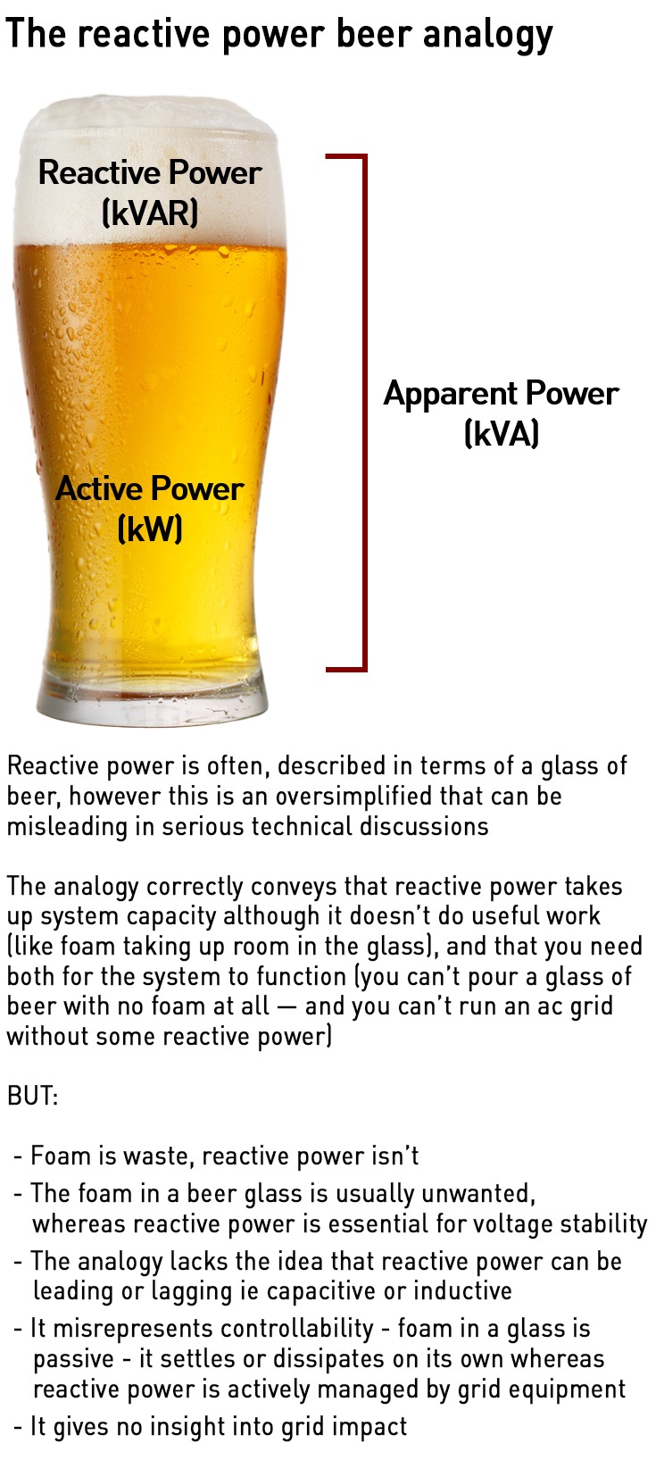
Not being able to properly explain reactive power is common in the energy industry – ask a dozen people to explain it and you’ll get twelve different answers. Most will reach for the beer-glass analogy where real power as the liquid and reactive power is the froth, or mutter something about “energy sloshing back and forth” on the grid. More sophisticated responses will mention capacitors “injecting vars” and inductors absorbing them. These phrases are repeated so often that they’ve become folklore. Unfortunately none of them describes what actually happens in power grids.
“Vars” in particular is an accounting fictions that obscure the underlying physics. And because we’ve replaced understanding of the physics with shorthand, we now incorrectly believe that anything producing current including batteries, solar inverters, or a clever algorithm, can perform the same stabilising role as the electromagnetic machines that built our power system. This misunderstanding could one day cost us the grid.
The volt-ampere was invented as a bookkeeping convenience in the 19th century – a way of quantifying energy oscillations between electric and magnetic fields in an alternating current system. It was never a physical thing, it was simply a way to balance equations. Over time, the mathematics replaced the meaning, and “supplying vars” became a commodity transaction rather than a description of an energy exchange.
To understand why this is a problem we need to get back to the basic physics. In this blog I am going to go back to absolute first principles and real physical things you could hold in your hand, to explain how our power grids really work and why failing to keep this front and centre means we may run headlong into trouble.
When the fields awaken: what exactly happens when voltage and current alternate?
Alternating current is created by the continual interaction between electric and magnetic fields. Inside every generator, a magnet (the rotor) spins inside coils of wire that form the stator. As the rotor’s magnetic field sweeps past the copper windings, it cuts through them, and according to Faraday’s Law of Induction, that changing magnetic flux produces an electric field in the wire. The electric field pushes electrons along the conductor, creating current. That current in turn generates its own magnetic field, so from the very first instant of generation, the electric and magnetic fields are bound together.
This mutual relationship of changing magnetic fields creating electric fields, and changing electric fields creating magnetic fields is exactly what Maxwell’s equations describe. A generator simply keeps those two fields interacting with each other in a perfectly timed loop – the magnetic field induces voltage, voltage drives current, and current sustains the magnetic field.
Voltage is the driver of current and should be considered more fundamental – a voltage differential creates an electrical potential difference analogous to gravitational potential at the top of a hill, which drives current flow (my GCSE and A-level physics teacher, who also looked exactly like Richard O’Brien of Rocky Horror Show and Crystal Maze fame taught it this way and it stuck). In this way, voltage is the manifestation of the electric field: an electric field creates electrical potential energy (voltage) which drives current.
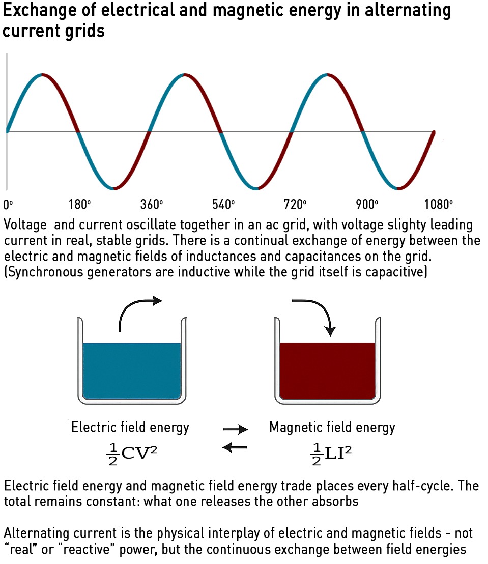
In alternating current, the electric and magnetic fields complete fifty full oscillations each second, meaning the direction of current actually reverses a hundred times every second, tracing the familiar sinusoidal wave of voltage and current. It’s this physical coupling between the electric and magnetic fields and not any notional “real” or “reactive” power that underpins the entire behaviour of the grid.
In an alternating-current system made up of synchronous machines, energy is continuously traded between two reservoirs: electric-field energy, stored in capacitances, proportional to ½ C V², and magnetic-field energy, stored in inductances, proportional to ½ L I².
As voltage rises, electric-field energy increases, while as current rises, magnetic-field energy increases. In each half-cycle of the voltage / current waveform, these stores exchange energy: what one releases, the other absorbs. This is the phenomenon people loosely refer to as “reactive power”. However it has no separate fundamental existence and cannot be “injected” or “consumed”. It is simply a reflection of how the system’s electric and magnetic energies interact.
What actually happens as voltage changes? Take a sine-wave voltage, assuming the grid is already energised and we’re taking a random snapshot (when the grid is first energised the behaviours are somewhat different as there is initially no load) starting at t=0 – voltage is zero and rising positive. Current and voltage are almost in phase (if they are perfectly in phase there is no active power, which is an abstraction too far!)
At this point, the electric fields of capacitors are already charged, and they begin to release energy into the circuit. Inductors, whose magnetic fields are empty, begin to absorb this energy as current builds. A quarter-cycle later, voltage reaches its peak. The inductors’ magnetic field are full and the capacitors’ electric fields are empty. As voltage falls, the inductors release their stored magnetic energy and the capacitors rebuilds their electric fields. This rhythmic exchange continue indefinitely.
Again, this is an abstraction. In the context of a synchronous generator connected to the grid, the “inductors” and “capacitors” are not separate components, they are distributed physical properties of the generator and the power system around it.
Generators are inherently inductive and its magnetic system dominates. Its coils, iron core, and the air gap between rotor and stator all store energy magnetically. The capacitance between conductors (turn-to-turn, phase-to-phase, and to ground) is tiny – it exists, but it’s orders of magnitude smaller than the inductive effects. In isolation, the generator behaves almost entirely like an inductor, and when it is connected to a resistive or capacitive load, current lags voltage because most of the energy is cycling in and out of the magnetic field, not the electric one. This is also why we say the generator’s power factor is lagging by nature – it doesn’t provide equal electric and magnetic energy exchange within itself.
To get a balanced exchange of energy between electric and magnetic fields, the inductive generator needs to be connected to a capacitor. Fortunately the power grid itself is capacitive in nature. Transmission lines, cables, transformers, and loads contribute distributed capacitance across the system. In steady operation, the generator’s inductive energy storage and the grid’s capacitive energy storage form the complementary halves of the ac oscillation.
When voltage and current are nearly in phase, as on a healthy grid, the electric and magnetic fields remain closely balanced and voltage is steady. At the theoretical extremes, 90o out of phase, the timing reverses, and the roles of capacitor and inductor swap. That is capacitors charge and inductors discharge when voltage rises and vice versa. (Most textbooks use the 90o out of phase scenario as the base case so will state that capacitors charge and inductors discharge when voltage rises, but this is not typically what we see on power grids where current and voltage are almost perfectly in phase.)
In addition, in the near-in-phase, power-delivering case typical of power grids, the capacitor is not just storing and releasing reactively, it’s participating in the transfer of real energy through the circuit. At t=0 V=0, current is flowing into the load and the system is delivering real power. The magnetic field in the inductive parts (coils, lines) is growing, ie inductors are charging. The capacitor’s voltage is near zero, but its “plates” (eg the power line and the ground) already hold charge from the previous cycle.
As voltage rises, current is still flowing in roughly the same direction, so the capacitor’s upper plate loses charge (it discharges) helping to drive current forward and support the voltage rise. The inductor simultaneously absorbs more current and stores magnetic energy.
The balance of shadows and light: what “voltage support” really means
In a stable grid where current and voltage are almost in phase, when voltage increases, current increases and the electric field falls as capacitances discharge. Magnetic fields rise as inductances charge. The relationship between supply and demand interacts with these relationships: as demand increases, the current drawn rises so electric energy falls and magnetic energy rises.
As energy is drawn from capacitances to meet the additional load, this energy is converted to active power (a grid engineer would say the reactive power falls). Now the magnetic fields in the circuit dominate. This manifests as both a phase shift between voltage and current, and a reduction in peak voltage amplitude. Because magnetic energy now dominates, the system behaves more inductively. This means current begins to lag voltage – it takes a little longer for the current to reach its peak because more of the energy is cycling through magnetic fields.
The reduction in the energy stored in the electric-field also means the outright magnitude of voltage drops ie not just as part of the alternating cycle. Any reduction in electric field strength translates directly to a drop in line voltage. This is why, in simple terms, when a big load is turned on, lights dim momentarily – not only phase but also the absolute potential difference falls because charge is being drained from the distributed capacitances.
A synchronous generator senses this in two ways: mechanical drag where the shaft slows fractionally because electrical torque has increased (frequency effect), and electrical field weakening as the terminal voltage falls because system capacitances have discharged. The automatic voltage regulator in the excitation system detects the voltage fall and immediately increases excitation current in the rotor field. This strengthens the generator’s internal magnetic field, pushing more electric-field energy (voltage) into the system, replacing what was drained, and restoring both the phase angle and peak voltage level to their previous state.
At the same time, the mechanical governor increases torque to restore frequency, closing the loop on both axes – voltage stability via excitation, frequency stability via torque.
The same magnetic energy that stabilises voltage also provides short-circuit strength – if voltage collapses locally, the collapsing field drives a surge of current that resists the change, anchoring the waveform. This natural elasticity is what makes a synchronous machine a stabilising presence.
The shift from field language to “vars” detached operators from physical reality. Once reactive power was treated as a tradable commodity, it became tempting to assume that any current-producing device could deliver it – if the grid code asks for a certain “var capability,” a battery inverter can be programmed to meet the number, so why not use it instead of a generator?
Because the physics isn’t the same. A generator alters magnetic flux, while an inverter simply alters a control angle in software. The first releases or absorbs real field energy; the second merely recalculates its current vector – inverters have no magnetic component to play with. That distinction doesn’t matter when nothing is wrong, but it matters a lot when the grid is disturbed.
The silent gatekeepers: how inverters actually work
Now we understand what synchronous generators are, we should do the same with inverters. When people talk about “power electronics,” they often picture racks of mysterious black boxes. But inside those boxes are simple transistor – tiny pieces of doped crystal acting as controllable valves for electrons. Every inverter on the grid, whether in a home battery or a 400 MW converter station, is nothing more than thousands of these valves turning on and off in carefully timed patterns.
These devices start with the raw material which is silicon. Silicon is a natural insulator (ie does not conduct electricity). Each silicon atom shares its four outer electrons with four neighbours, forming a rigid crystal lattice with no free electrons to move, which is why it is electrically inert – it can hold charge, but the absence of free electrons means current cannot flow.
To make silicon useful in power electronics, tiny quantities of other elements are introduced in a process known as “doping”. This involves adding a few atoms per million to subtly change the crystal’s electrical characteristics. Phosphorus or arsenic have five outer electrons instead of four – when added to silicon, each dopant atom has one spare electron not needed for bonding. This electron can move freely through the crystal, allowing it to conduct electricity. The result is n-type silicon, rich in mobile negative charge carriers.
Boron or gallium, by contrast, have only three outer electrons, leaving one missing bond – a “hole” that behaves like a positive charge carrier moving in the opposite direction. That creates p-type silicon. When n-type and p-type regions are placed next to each other, electrons and holes diffuse across the boundary and recombine, leaving behind charged atoms that form an internal electric field known as the depletion region. This junction conducts easily in one direction but resists current in the other and is s the principle of a diode, the building block of all transistor behaviour. A transistor adds a third terminal that controls this internal field.
In modern power devices that control terminal is the gate, separated from the silicon by a wafer-thin insulating oxide. When a small voltage is applied to the gate, it pulls charge carriers into a channel beneath it, linking two main terminals (the source and drain) so that current can flow. Remove the gate voltage and the channel collapses, blocking the path again.
It’s easiest to imagine the transistor as a drawbridge for electrons: the gate voltage lowers the bridge, allowing charge to cross; remove it, and the bridge rises, cutting the path. There are no moving parts, just electric fields shaping the flow of electrons within a crystal only microns thick.
Each power transistor chip is a small square of silicon or silicon carbide mounted on copper for heat removal. It’s bonded to metal leads and sealed in a ceramic case, about the size of a coin or postage stamp. If you pick one up, it feels cool and inert, but inside it’s capable of switching hundreds of amps and blocking thousands of volts. An industrial inverter or grid converter contains hundreds of these modules, clamped onto water-cooled plates to remove the heat produced every time they switch.
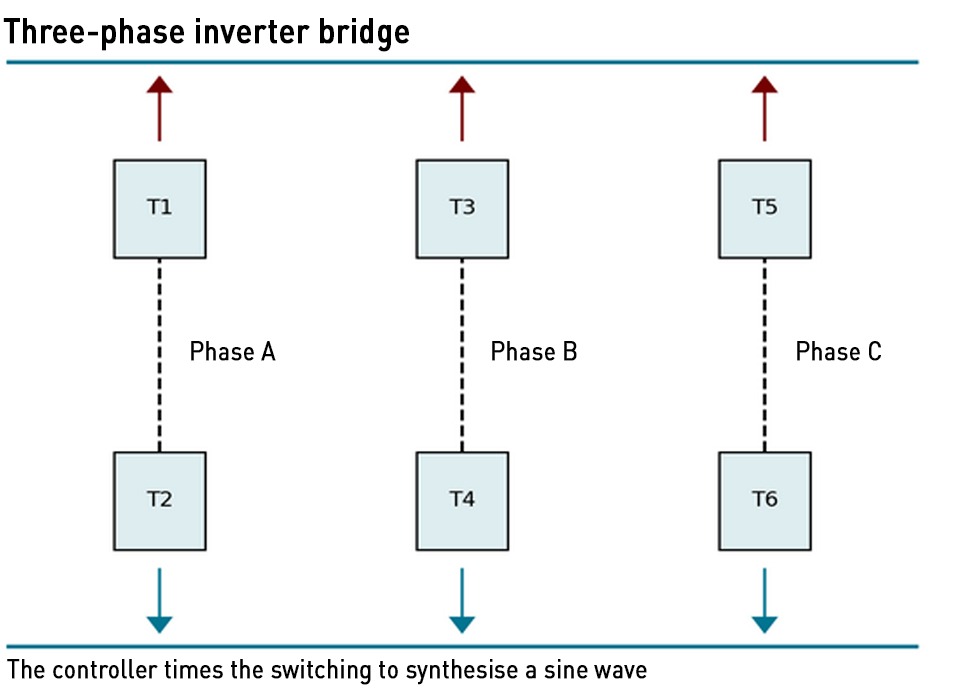
Six transistors are arranged in three pairs, one for each phase of the output. Each pair acts like an electronic switch, alternately connecting that phase to the positive or negative side of the inverter’s internal dc supply. A digital controller switches them on and off tens of thousands of times per second using pulse-width modulation. By varying how long each transistor stays on or off, the controller makes the average output voltage follow a sine wave.
A simple L–C filter smooths out the pulses, and the result is clean alternating current ready for the grid. (An L-C filter consists of a combination of inductors (L) and capacitors (C) to cut or pass specific frequency bands of an electric signal. Capacitors block dc currents but pass ac more easily at higher frequencies. Conversely, inductors pass dc currents as they are, but pass ac less easily at higher frequencies. As capacitors and inductors are passive components with opposite properties combinations of them can reduce noise in electrical signals.)
When a waveform is displayed on a scope trace, what is actually visible is the collective behaviour of hundreds of tiny crystals, each opening and closing in nanoseconds under software control.
This sounds wonderful but there are hard physical limits inside the silicon. Each transistor has strict physical boundaries defined by materials science:
- Voltage limit: set by how strong an electric field the crystal can withstand before it breaks down and conducts uncontrollably
- Current limit: defined by how much heat can be drawn away before the silicon melts or the wire bonds fuse
- Switching speed: governed by how quickly electrons can move in and out of the conduction channel without causing localised charge buildup and failure
The combination of these constraints defines the safe operating area and is designated by a triangular patch on every transistor datasheet. Beyond these limits and the device will fail, usually instantaneously and irreversibly. This is why inverters have hard current ceilings, intricate cooling, and multi-layered protection circuits.
At any moment, the inverter’s total output current is limited by the sum of the currents through its transistors. That total current must cover both the part delivering real power and the part maintaining the grid’s electric-magnetic balance (the “field” component):
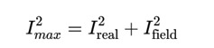
If the grid voltage dips and the inverter has to increase its “field” component to help restore electric energy – it can only do this by reducing its real-power output. Unlike a synchronous generator which can exchange energy between its magnetic and electric fields without affecting mechanical torque, the inverter has only one resource: current. Every ampere of current devoted to supporting voltage is an ampere no longer delivering energy to the grid.
The dangerous illusion of vars
The key difference between an inverter-based generator and a synchronous generator is that the latter stores energy in its magnetic field and can exchange it dynamically with the grid. A transistor stores nothing, and has no magnetic field. Even though wind turbines do posses magnetic properties, they are not synchronised to the grid (because they cannot rotate at a stable speed), and the very existence of the inverter interfacing with the grid means this magnetic resource cannot be used for grid support. And even if a device that could access this resource could be developed, it wouldn’t be very useful since wind turbines tend to be located in remote areas and voltage support needs to be local: supporting voltage in the middle of the North Sea isn’t all that helpful for the gird as a whole.
So inverter-based generators can release charge from a capacitor or control current through an inductor, but they have no internal electromagnetic inertia. So when voltage or frequency changes faster than its control loop can respond, they cannot “push back” naturally. The inverters just saturate and drop out.
Grids that were once stabilised by tonnes of metal, are increasingly governed by milligrams of doped silicon. Their operation is precise, efficient, and in many ways, astonishing, but they have no physical “spring”. When engineers say an inverter is “supplying reactive power,” nothing mystical is happening – the inverter isn’t injecting invisible “vars” into the grid, it’s simply redirecting a portion of its finite transistor current away from delivering real energy and towards supporting the grid’s electric field.
Inside the silicon, the control system tilts the current vector so that part of the transistor’s current now flows out of phase with the voltage. Mathematically, that looks like “reactive power” concept that describes the exchange of energy between the electric and magnetic fields of synchronous generators. But physically, it’s just the controller commanding the electron valves to momentarily spend more of their available current helping the electric field rather than the mechanical load. Because total current is capped by the transistor’s material limits, this trade-off is absolute. There is no separate pool of “reactive power” ie energy stored in the magnetic fields of inductive devices including synchronous generators, only a redistribution of current within tight atomic constraints.
Frequency reflects the balance of active power: generation versus demand. When inverters divert current from real power to field control, total active generation falls. If thousands of units respond identically to a voltage dip, as most are programmed to do, the system’s real power output will collapse even as voltage recovers. The immediate consequence is a frequency drop.
A control philosophy that treats voltage and frequency as independent channels suddenly discovers that they are not: both draw on the same finite current vector. In fact, we can borrow from a finance concept here: “dynamic conditional correlation” describes the way in which normally uncorrelated assets can become correlated under market stress. During the 2008 financial crisis a need for liquidity drove banks to sell assets of all types chasing cash, meaning that assets whose values were normally uncorrelated, all lost value at the same time due to the selling pressure.
Similarly, a voltage response relying on inverters diverting current from active power to voltage support will cause a frequency drop in a way that is simply impossible in a grid based on synchronous generators which separate these roles naturally – torque governs frequency, excitation governs voltage – but converters cannot.
This risk is baked in to our grids. Modern grid codes require all inverters to follow near-identical “volt–watt” and “volt–var” curves. When a regional voltage sag occurs, every device interprets it the same way and responds in the same way at the same time. Their combined action releases electric-field energy but simultaneously strips the grid of active power. What begins as a mild voltage disturbance becomes a coordinated frequency collapse. No one planned this but it’s a by-product of abstraction. Designers thought in terms of reactive power numbers rather than field energy and never noticed that the two controls are drawing on the same resource.
So when people assert, as they have done in relation to the current voltage control issues in Spain, that batteries and grid-forming power electronics can replace conventional synchronous generators, providing both traditional inertia and voltage support, they are not only wrong, they risk turning a small fault into a massive grid failure.
Exorcising the grid
A synchronous generator’s magnetic and mechanical systems are physically decoupled. It can transfer energy between its rotor field and the grid’s electric field without touching the mechanical torque that defines its active power. This separation is what makes synchronous generation intrinsically stable: voltage control doesn’t interfere with frequency control. It’s also what gives the grid its electromagnetic “stiffness” – the ability to resist both voltage and frequency perturbations simultaneously. Remove that separation and the grid becomes brittle.
Once inverters dominate, voltage and frequency cease to be independent dimensions, they merge into a single fragile dynamic limited by semiconductor current and software timing.
The entire modern stability philosophy is based on separate voltage and frequency control loops, and separate service markets for “reactive” and “active” power. But in an IBR dominated grid that is no longer true.
Imagine a sunny afternoon, low demand, high renewable output. A transmission fault causes a brief voltage dip. Every inverter in the region responds within milliseconds, releasing electric-field energy and cutting active power. Frequency falls, so other controls react, but they’re already at their current limits. Protection relays trip, and the disturbance cascades. The system fails because its components all did exactly what the “var” abstraction told them to do.
System operators need to get back to the physics and remember that “reactive power” is not a product – it’s not even real in the way they think it is. It’s not a “thing” that can be injected to or absorbed from the grid, it is simply the visible trace of the continuous exchange of energy between electric and magnetic fields. Understanding that exchange – how capacitances and inductances behave as voltage and current evolve – is essential to keeping the grid stable.
Synchronous generators manage it naturally, and for free, but inverters can only imitate it within narrow limits, and at a cost (haircutting active power output ie selling less electricity to consumers). Designing a secure power system requires recognising that limitation and maintaining enough true electromagnetic machinery to anchor the fields of the network. Until we do, we’ll continue to model our grid in made-up units, unaware that the physical system underneath speaks an entirely different language.
Thats a very good article, easily understood and something I was curious about, by using synchronous condensers, does this imitate some of the behaviours of synchronous generators?
Synchronous condensers are almost identical to synchronous generators – same rotor, stator, excitation system, and electromagnetic behaviour but with two key differences:
1. they consume electricity from the grid to keep the rotor spinning instead of using a prime mover such as gas or steam
2. they are controlled so that the net active power output is zero (or very close to it by maintaining a phase angle at or near zero): they neither generate nor absorb real power on average, but their excitation is adjusted to strengthen the electric or magnetic fields as needed to support voltage
A good summary of the physics without the distracting math, Kathryn. I have been following the issue of rotating vs synthetic inertia for some time. The issue does not seem to have been getting much attention from the press where I am (Japan). It sounds to me as though the claims made by the renewable energy lobby have been downright misleading: they dismiss the worry about the scrapping of rotating inertia by claiming that it can be created artifically using grid-forming inverters, but the examples they give are either small scale (island grids) or laboratory level scale. Fortunately, the Japanese government has not been foolish enough to make Net Zero mandatory, although it is succumbing to foreign “progressive” pressure in setting “decarbonization” targets. Japan also has 54 nukes that it is gradually restarting following Fukushima, so it has plenty of baseload backup if it needs it. You’re doing a great job of providing common sense and hard facts to counter the Net Zero cult cancer in the UK. Keep it rotating!
Thanks Tim.
I agree – the green lobby misleads in 3 big ways:
1. renewables are cheap
2. batteries can fully back up wind and solar
3. IBR can replace synchronous machines for grid stabilisation
None of these claims is true for large-scale grids. Yes, you can do all of that in a micro grid where the size is small enough for voltage to be the same everywhere and the total load is both limited and not essential (eg it would be foolish to run your home on this basis if a family member relies on a ventilator for breathing. You’d really want a diesel generator backup)
“The volt-ampere was invented as a bookkeeping convenience in the 19th century…” Should that not be volt-amp-reactive?
Another excellent and informative article.
One question, could inverters not be coupled with multiple large inductance wire-wound resistors or even flywheel “generators” to accurately mimic the inductive behaviour of traditional turbine based generator stations?
In principle, yes — you could add external components like inductors, resistors, or even flywheels to try to mimic the dynamic behaviour of synchronous machines. But in practice, each of those options has fundamental limits that make them only a partial substitute, never a true replacement.
Adding big inductors at inverter terminals can imitate some aspects of synchronous behaviour as they slow down current changes and give a little bit of “electromagnetic inertia.” They smooth the inverter’s current output, reducing harmonic noise and making the current–voltage phase relationship behave a little more like a machine winding.
But the amount of inductance needed to match the energy exchange of even one synchronous generator is huge – the coils would be physically massive and lossy. They store magnetic energy but don’t create torque, so they can’t help with frequency stability – only a bit of voltage stiffness. Their behaviour is linear and passive, so they don’t “push back” dynamically the way a synchronous generator’s field and rotor do. So inductors give you a mild damping and filtering effect, not true grid-forming capability
Flywheels do store rotational energy, so they can supply genuine inertial response: they can push back against frequency changes. If you couple a flywheel to an inverter through an electrical machine (a synchronous motor/generator), you create a virtual synchronous machine. These systems can deliver real electromagnetic torque through the inverter, mimicking the swing behaviour of a real generator. But you effectively re-create a synchronous generator, just driven mechanically by a flywheel instead of steam or gas. They’re expensive, complex, and lose the efficiency advantage of pure solid-state conversion.
The coupling through an inverter still limits the dynamic range as the inverter’s transistors must carry all the current, so the total response is capped by semiconductor limits.
Still, hybrid systems like this do exist, for example, flywheel-based grid-forming devices are used in some microgrids and island systems to stabilise voltage and frequency. They can work well locally but aren’t practical at national-grid scale.
Totally agree. Thank you Kathryn.
The elephant in the room of course is whether power generation using fossil fuels is really causing catastrophic global warming. There is no evidence that it is and anthropogenic emissions are a minor contributor in changing climate compared to orbital changes, tilt angle changes, sun activity, cloud coverage, ocean currents, etc.
Agree.
The elephant in the room of course is whether power generation using fossil fuels is really causing catastrophic global warming. There is no evidence that it is and anthropogenic emissions are a minor contributor in changing climate compared to orbital changes, tilt angle changes, sun activity, cloud coverage, ocean currents, etc.
Thank you again for your customary lucidity. The Beeb’s reporting is at the limit of shallowness.
Great article thank you.
How about adding large wire-wound. Inductors to inverter circuit outputs or even parasitic flywheel generators to mimic the performance of steam turbine driven generators?
Static VAr compensators use triacs to switch in more or less capacitance or inductance to tune voltage; they are cheaper than synchronous condensers and require less maintenance (no moving parts) but lack the condenser’s inherent inertia.
That dusted down my power engineering degree knowledge and needed two read through to reacquaint myself so thanks for taking time to produce.
As an aside im interested in early development of UKs power system and they made extensive use of motor alternators before transformers became reliable and affordable. So clearly not the most efficient way but perhaps we need renewables to insert an motor alternator set before they connect to the grid so they can truly mimic what a turbo alternator does. Or is this what a synchronous compensator endeavours to do?
I’m puzzled.
If the energy stored in a capacitor is 1/2 C V^2 and the energy stored in an inductor is 1/2 L I^2 then if voltage and current are almost in synch, the energy stored in both capacitors and inductors will increase at the same time and decrease at the same time. Why is there an exchange of energy between them?
While your article raises important points about reactive power and voltage stability, two technical claims deserve clarification:
1. Modern inverters can provide reactive power.
Contrary to the statement that today’s inverters are unable to supply VARs, virtually all grid-connected PV, battery, and wind inverters deployed under recent network codes (e.g. EU Regulation since 2016) are capable of both capacitive and inductive reactive-power control. They can operate at fixed or dynamic power-factor setpoints (Q(U), Q(P) curves) and are routinely used by TSOs and DSOs for local voltage regulation. The limitation is therefore not technical capability but system coordination and remuneration.
2. Capacitors, reactors, and modern power-electronic devices do supply reactive power—just differently from synchronous machines.
Passive components like capacitor banks and shunt reactors provide steady-state reactive support, while power-electronic systems such as SVCs and STATCOMs offer dynamic, fast-acting reactive-power control equivalent to (and often faster than) synchronous generators. The real distinction is that synchronous machines also contribute rotational inertia and short-circuit strength, not that other devices fail to provide “real” VARs. You can also have both with synchronous condenser or more recently developed asynchronous rotating energy system stabilizer (ARESS).
In summary: Reactive power from non-rotating sources is entirely real and essential; what changes is how it’s controlled and integrated, not whether it exists.
Terrific explanation. Really excellent. Thank you for writing it.
There are several solutions, and a choice has been made to use synchronous condensers.
It would have been possible to couple the large wind farms to a motor-generator system for each wind farm, where the power from the wind farm is fed into a motor to drive the generator, where the generator would have produced the synchronous, non-IBR output. The same is true of the large PV solar farms.
One has to question which would be the cheapest option, and would shift the responsibility for the investment and grid control, away from separate synchronous condensers to the wind/solar PV farms themselves.
It may yet be proved that synchronous condensers aren’t as financially efficient, but would mean that wind farms would need to be retrofitted with equipment for synchronous output.
There are multiple ways of dealing with the issue, different choices can be made in the future as the grid changes.
“couple the large wind farms to a motor-generator system for each wind farm”
Would this mean that there would not be the requirement to upgrade the grid infrastructure as much.
There are grid upgrades due to putting so much wind generation in Scotland and off-shore, then there’s all the new generators where there are many more distributed suppliers that need connecting over the few large gas/coal/nuclear power stations previously. That’s just the generators. Also with changing to heat pumps and electric cars, local networks are going to need to be upgraded at some point. Then there’s the higher power users, where they’re trying to encourage users to self-generate rather than take more power from the grid. Car charging stations are one point, where they want the stations to have solar PV and batteries, such that the instantaneous current draw is limited where the station batteries are trickle charged at a lower current/power rate or on off-peak electricity. Grid upgrades can’t be avoided, but what upgrades and when and how many or current/power capacity can be minimized by other technology being installed.
Would motor-generators for wind farms reduce the grid upgrades? Not a lot, if at all, it’s only a different alternative to the installation of the synchronous condensers.
I guess you could call the plans to build large volumes of pumped storage along the Great Glen as exactly that. Indeed, the system on the island of El Hierro often operates in this way. Excess wind generation is used for pumping, but the limited reservoir capacity (actually of the lower reservoir) means that the water is returned without generating down the twin penstock. The pumps (which can also operate as generators if engaged when the flow is downhill) provide inertia and stabilisation.
Pumped storage also performs this role in mainland Spain. Unfortunately most of it is in the mountainous North, a long way from the IBR based solar surpluses in the SW, so it was literally badly placed to help prevent the gran apagon on April 28th.
Exactly, it’s getting these sorts of synergies that can bring the system cost down, but as you’ve pointed out, geography can sometimes be inconvenient.
It sounds like you’re proposing something like a Ward-Leonard generator set. But then you’d have the problem of not enough electrical inertia. Remember current systems may be rated at 300MW and above, they have enough rotational inertial mass. Whereas a wind farm would not be capable of providing such a constant load.
“It would have been possible to couple the large wind farms to a motor-generator system for each wind farm…”
But how much more convenient for the wind farm developer and lobbyist if the cost of making their product reliable can be passed off to someone else, Tim?
It’s what happens when you get early adoption of technology that isn’t fully developed for what it needs to be. There are synchronous wind turbines in production now, and rather than a motor-generator setup for the whole wind farm, or inverters, there are individual turbine solutions.
https://www.windflow.co.nz/Grid-Stability.htm
Wind turbine technology isn’t mature yet. It’s only mature for the specific technology that has been used previously. I think there’s a few more iterations for the generator part of the turbines still to go.
Of course they’ll start with the cheapest technology available, but then as problems occur, there’s always the redesign needed and then the cost-benefit analysis, until the cheapest solution is found that meets specifications. We might yet see the synchronous condensers disappear from the grid as integrated solutions are found.
With early adoption of wind turbines, it was all due to economics of sizing, getting the turbine diameter as large as possible for economic efficiency. There’ll be the electrical stability phase to go through where new designs will start to dominate eventually.
Wind turbines will get more sophisticated. Just think, we’ve had cars for over 100 years now, and the engine technology has changed massively. What will be the differences in wind turbines in 100 year’s time?
I can’t predict, the number of different solutions and their costs are unknown, because of the uncertainty with grid behaviour, it’s something that you can only develop as the whole grid matures/changes.
If fusion comes on stream………in 30 year’s time is it?…….you might see all the wind turbines disappear anyway.
Kathryn, you said in one of your replies, “They can work well locally but aren’t practical at national-grid scale.” We then have to question if it would be better to break the national grid up into smaller self-contained cells, that can provide supply to connecting areas, but are, for all intents and purposes, self-sufficient?
Is the problem that for renewables, the national grid is too big an electrical beast to manage, so we need to tame it by making it into a herd of smaller, more manageable beasts, that can’t bite back?
Would having smaller cells make the whole thing more resilient? A cell may go down, but not the whole thing.
As I said before, there are a number of different solutions, no one is “right” but they have different characteristics, cost and benefits, and different choices could be made.
“Is the problem that for renewables, the national grid is too big an electrical beast to manage, so we need to tame it by making it into a herd of smaller, more manageable beasts, that can’t bite back?”
Tim, I’ve been saying for years that someone (I don’t know who – a lone ministerial adviser perhaps, and a gullible minister) wants as many domestic users as possible disconnecting from the grid and going it alone with their own power gen, or maybe street by street gen. But do we want a situation where every standalone user is responsible for the maintenance of their own system, rather than just calling a power outage hot line? Then I remember that politicians are always banging on about needing thousands more electricians for the imminent “renewable energy superpowerness”- is this why? It certainly works for me as I’m in the business. It’s my guess that a power grid and its maintenance team is more workable than thousands of houses having to organise their own maintenance, even with less widespread outages. Plus, where does that leave people who can’t install their own systems? If you make the power system more diffuse (network wind & solar & batteries) people who cannot afford to go it alone will be left to pick up a larger share of the ever expanding grid. I know I’d crack the proverbial if I was paying a monthly power bill which includes connection fees and capital costs for network expansion, while lord muck down the street never sees one, disregarding the capital cost vs. monthly charge perspective. The answer is that we need a more concentrated source of energy, not a less. Now, if there was such a thing as a domestic nuclear reactor… Anyway, I’m only spit-balling, and I’ve gone on a bit, but you never know.
One of the major economic differences is that instead of spending money on so much fuel, as imports, you’ve got more grid, supplier and user equipment to install/maintain/repair/replace, where employment is much higher. It’s a major switch from fuel costs to staff costs and capital costs.
For residential, if the systems are designed properly, it should be less annual maintenance than a gas boiler, but there will be times when instead of having no heat because your gas boiler has broken down/needs replacing, it’s (most likely) your inverter, or heat pump or CHP system (engine or fuel cell). With CHP, the amount of maintenance will depend on the technology used, and for some systems it won’t be any different to gas boiler maintenance schedule, i.e. annually.
As far as I can see, for many people it would be a change from gas maintenance to electrical maintenance, but if we get to CHP, with hydrogen or some other gas, we’ll still need the gas engineers as well. It might not be heat pumps as they are so expensive to install.
People already have to organise maintenance for gas boilers, and their replacement, so it’ll not be too different overall, but employment should be greater than now.
We’ll still need the centralised renewables for supplying cities, where in cities space for renewable installations may be limited. It might get more expensive than now to live in a city, but if they build energy efficient buildings, it shouldn’t.
They could start to prevent residential consumers from grid-tying the solar PV, and insist on battery installation for each residential solar PV, to remove some of the variability of that supply, and the adverse effects on the grid, but again there are multiple ways of doing everything. You could still have grid connection, to act as a back-up for your own system when doing maintenance, or as supplementary trickle charging, such that peak current demands are reduced. for each household, and the shift to off-peak, or when there is greater supply from the variable renewables, e.g. daytime summer.
Theoretically if the politicians would stop handing out subsidies, the economic technologies would be installed and it would change naturally as people find the real economic benefits. There are economic renewables and installation strategies, it’s just that the current political thinking is non-economic and forcing fitment at an uneconomic rate and strategy.
With CHP or heat pump systems, you’ve got gas, mechanical and electrical systems. Just a bit more training for the present gas boiler engineers.
Tim:
Your idea, is how things used to be before the whole system was nationalised.
I reckon a distributed system like the old days would be a non starter today because the authorities would regulate the bejesus out of it.
I think we’ll end up with all the rural areas decentralized doing self-generation semi-off-grid possibly with CHP, and the cities all on centralized national grid. The units may be smaller, down to individual homes, as they separate off to reduce the cost of power, if the current electricity price trend continues. Far more distributed than the old days, not at district level, but down to individual homes and businesses. If it gets really bad, even the cities might slowly find a way to get off-grid.
Does that mean that rural customers get expensive power and have to suffer regular inconvenient/life-threatening outages and urban users get cheap reliable power?
I put a condition on it, if the current electricity price trend continues. If you have the grid there as a back-up, there are no life-threatening outages. Things can be as reliable as a solar PV inverter – 12-15 year reliability. Residential users can manage almost exclusively on solar PV for at least 6 months already, it’s not too difficult, and very cheap, to increase solar PV maximum power over 4kw, e.g. 10kw to get more autumn/spring penetration and do CHP for winter. It’s an alternative, not predetermined, it depends what happens over the next 5-10 years, but may become a reality. It would only be done if it were proven to be cheaper and with sufficient reliability.
Hi,
The article is rather misleading as it contains two, maybe three, underlying assumptions which whilst practically true are not a feature of the technology. Those underlying assumptions are that (a) a rotating machine is not normally operating at its maximum short term rating and (b) an inverter is normally operating at its maximum short term rating and (c) there is no energy storage behind the inverter.
The fundamental issue is that rotating machines are robust, heavy devices with a big thermal time constant, backed with a big energy store (their own rotational inertia). You can get a rotating machine to deliver much more than its long term rating for short bursts without damage – they are usually operated massively (probably a factor of 5, 10 or more) below their short term (e.g. < 1 minute) ratings.
Inverters are much more fragile. They don't feature lots of thermal mass so when you overload them they heat up very (very!) quickly (in seconds rather than minutes). The technology is such that generally their short term and long term ratings are very similar. In addition, inverters which are not connected to energy storage systems have no intrinsic energy store which would allow them to deliver any additional power beyond the capability of the underlying generation (which in the case of solar has pretty much zero stored energy and in the case of wind, so far as I am aware, no-one actually uses the inertia in the turbines).
There is nothing stopping someone designing an inverter which mimics a rotating machine (give or take the extent to which you can filter out the inverter switching noise). The issue is that the inverter will be much bigger (and more expensive) than everyone would expect because you will end up with an inverter with a rating several times the size you thought you needed. In addition, the inverter would need the energy storage required to mimic that embodied in a rotating machine.
The issue here is not the underlying technology, it is that the underlying technology and its application has lead to economic decisions about the form in which that technology is delivered. The main reason for this is that the energy delivered by inverters usually comes from a source which has no energy store so there is no point in over-rating the inverter so as to be able to match a rotating machine's fault currents or inertia because there is nothing to deliver the energy to the inverter which would be required to do that.
Battery systems also tend to fall into a similar camp – their inverters are generally designed to operate at "energy storage" power levels, not fault / inertia power levels because the battery system operators aren't selling fault ride through / inertia capability, they are selling longer term energy storage.
As with everything, technology is not necessarily the problem, it is how you use it…
All of this is true, however it should be noted that most inverter systems are not run right at the edge of the maximum current the switching semiconductors can handle. There is a balance between sizing the system, thermal management, and equipment lifetime. It is theoretically possible for an inverter based system to be running at its maximum steady state output but still be capable of increasing its total current in order to keep active power steady while providing voltage support. Of course this is only possible if some reservoir of energy is available to draw on. In practice therefore solar and wind resources are unlikely to be of much help since they are pushing all the energy being produced through to the grid already (unless there is a grid constraint). Battery systems however will be able to deliver additional energy for a period of time. In fact, many solar PV inverters are deliberately undersized relative to peak input DC power for cost optimisation reasons.
While there are currents sufficiently high to destroy the switching transistors and from which they must be protected, the actual steady state operating limit is based on a thermal system constraint and optimising system lifetime. Depending on the heat sink and active cooling of the system, it may be capable of controlled overload of 10% to 20% for quite a while.
However there are two problems with this:
1) It actually has to be configured on an equipment level to do this, the grid code has to require it, and it has to be tested or it might not work when you need it.
2) If the system is capable of only short-term overload (say, 5 seconds) and the disturbance lasts longer than that, you could have a catastrophic disturbance where a disturbance starts, a large number of battery backed inverters act to oppose it, and then all suddenly drop off simultaneously.
For residential, many PV inverters aren’t undersized because there is a maximum power output of 3.68kW that is allowed to be exported on a single phase connection, i.e. you are not allowed to have a bigger inverter. Having greater panel array output means that instead of having a loss of power output with cloud cover, the higher power output can be maintained. One example is a Solis 3.7kW single phase inverter that can take 5.4kW of panel input. It gives income enhancement and also allows for panel degradation. A 5.4kW array degrades to about 4.3kW in 25 years. The obvious question to ask is if it would be better not to lose that potential 1.7kW (almost 1/3rd of the peak) so early on in the life of the system? We’re starting to build inefficiencies back into the system, but does it matter, if the panel cost is so low, and the sunlight is free? Why not have 10kW array, that can be switchable, for those low light conditions, or on a separate circuit, just to act as a battery charger? When does it become uneconomic to install 2x, 3x or 4x panel output over inverter output, if it allows you to work all year round?
£62 inc VAT for 450W panels now, just £744 for 5.4kW array……dirt cheap now. One has to ask if it is possible for prices to get any lower?
£1488 for a 10.8kW array, £2,232 for a 16.2kW array……..can you get solar PV to work all year round, with no mains supply needed, when you haven’t got a heat pump?
If you have a heat pump working off solar PV, from a separate inverter running from the battery, not through the grid-tied 3.68kW inverter, how much cheaper would it be to run?…….It’s almost getting to free heat when running!…….it’s just the initial cost of the heat pump system that is so high.
With battery backed grid-tied inverters, the variability of sunlight input and thus the variability of array output can be attenuated, such that output becomes significantly less variable. Perhaps the design specifications and legislation for residential connections will change to solve the variability of solar PV, such that battery installation will become compulsory with residential grid-tied inverters.
Very good article, currently studying for my level 3 electrical installation, only this week we looked at inductive reactance and capacitive reactance, happy to say I was able to follow the article and you’ve explained it in a way that it now makes a lot more sense.
If only Miliband had half your brain and grasp of how electricity and our national grid actually work! Thanks again for your thorough explanation Kathryn.
All inverters are coupled to an inductor – namely the big transformer that attaches it to the grid. But this inductor cannot store energy for more than 10 milliseconds – because of the 50Hz AC grid. It has to release all of its stored energy each time the current drops from its peak through the zero crossing.
An inductor resists a change in current – by creating an opposing voltage “V = L dI/dt” . You cannot add an arbitrartily large inductor to the output of an inverter, because this opposing voltage would be too large, and would destroy the transistor bridge due to overvoltage.
Whereas a rotating synchronous machine can store energy for multiple mains cycles – it resists changes in rotational speed (frequency) by producing an opposing torque “T = J dω/dt” which absorbs or releases power proportional to the rate of change in frequency. This damps any oscillation in frequency, but also in voltage, because the generator’s voltage source is also proportional to rotational speed. (assuming the excitation field is kept constant, that is. Which on the scale of a few seconds, it generally would be)
The elephant in the room with wind and solar surely is that they are hugely intermittent. As in 18 hours per day for solar in the winter and often 2 weeks or more off during Dunkelflaute for wind.
Thanks for the reminder! Back to 1st semester field theory in the 1980’s for me and explains what I had thought.
You do start to doubt yourself, though when there are so many people who should know better absolutely convinced grid forming inverters can dominate and stabilise a grid here in Australia.
A very interesting article. The slightly incorrect statement that the grid runs a 50 cycles amused me because the North American grid runs at 60 and the difference makes a lot of equipment un-transferable. 10 years ago I bought residential heating boilers made in Holland for use in Canadian rental properties. For 6 long months they were a nightmare, failing or “faulting out” at irregular intervals, sometimes 20 minutes sometimes 2 weeks, driving me and my tenants crazy.
The boilers were internet capable and the Dutch engineers worked hard to fix the problem, linking to the boilers and watching them fail in real time. I would have liked to have seen the forehead slap when they realized that a control boards, fan motors and hydronic pumps designed to eat 50 hertz electricity may not like 60 hertz.
What I find interesting about all the grid upgrades is that if we get to centralized fusion power dominating, and all the distributed generation goes again, a bit like the voltage cycles in AC, going from distributed to centralized, back to distributed then back to centralized. If the government had actually thought out what the next stage might be, just like Kathryn has suggested Nuclear Fission, centralized, keeps the capital expenditure down, and keep the demand for raw materials down, so too would fusion. A number of grid upgrades would not be necessary, like all the work going into Scotland, with wind turbines everywhere, and not enough National Grid capacity to transmit the power south of the border. If we are going through a temporary phase of decentralization, would it not be better to keep all the renewable installations as end-user?
I’ve referred to the Beeching cuts before, and if we do get fusion working and some fission nuclear, where is the need for solar and wind farms going to be?
If we had stuck to just end-user installations where it is economic, plus allow some over specification to allow export, we could have had fewer grid upgrades, except for the addition of stability equipment. No AR rounds, no subsidies, no curtailment, no profit exported to international investors, no additional costs of crown property (seabed) leases, no land leased by land owners, because they’d only be installing for their own needs and with an power output allowance for exports. Electricity would have been cheaper.
If the governments, both national and local had just concentrated on economic installations themselves to reduce their own costs of operation, and to reduce their own CO2 emissions tally, and to gain some income from exports, where would we have been?
If the National Grid have to keep adding different grid services to solve various problems, there will come a time when they will look at the overall change and start to ask how to rationalize the whole thing. It will be interesting if it ever gets to that point.
With going from distributed to centralized to distributed and back to centralized, there will always be a case for distributed back-up when centralized fails, for critical services. It might be that we go through a period of centralized back-up for distributed power generation for many people, so there is actually a good case for having both distributed and centralized all the time. Strength and resilience in numbers and diversity.
I’m trying to encourage Ofgem to think in these terms – we started with a grid designed around the physics of ac, and are gradually converting it into something much less reliable, creating problems that require multiple layers of sticking plasters
My pushback on this is: is the climate cost of generating electricity with methane really worth all this cost and risk? Gas is not coal. It burns FAR cleaner. Maybe we should try to adapt to the climate impact of burning methane rather trying to stop doing it
And if people ask “what about people in Africa who will suffer the biggest climate impacts”? well at a recent conference, African delegates were very clear that they face a poverty rather than climate emergency and need to industrialise as a priority, using gas.
I think we need to major re-evaluation of the entire subject, with proper cost-benefit analyses and no assumptions around prevention vs adaptation, but evidence and data…
There’s one key question you could ask them:
Is it a good idea wasting money on curtailment, with too many wind turbines, not enough grid connections and only inverter based output, when instead we could have invested the money in synchronous wind farm output?
That should cover it. It’s the crux of the whole stability matter, and the money being wasted isn’t it?
Good luck. Always enjoy reading your blog, great stuff. I guess it’s why many government projects don’t go to budget, problems with specifications and management. Just don’t mention HS2.
Alternatively I suppose they could have just specified a synchronous condenser at each wind or solar farm. Damp all fluctuations at source, but would that be wasting money, where you can wait to see where the grid misbehaves, and then put a leash on the beast in that specific location…….choices, choices.
I’m certainly very impressed with the huge technical detail that you get through, very interesting reading and enlightening.
Each sticking plaster is employment and possibly economic growth. Do you think that they will see that as a bad thing?
We’ve got a reasonably stable grid. Like any government project, there are benefits, risks, costs and waste, nothing changes. If we get more nuclear back on the grid, will that solve any stability issues, with that constant reliable base of generation – a good 10GW baseline? At least we’ve got some progress on RR getting the SMR contract, and that’s a huge benefit and significant development. Things are looking up.
We can adapt to the increasing electricity prices in several ways, use it more efficiently, or cut down other expenditure if our budget is fixed, or we can do our own thing and go for much higher efficiency, but that increases our own capital costs.
Adapting to climate, less spent on winter heating, but starting to add in summer cooling, more solar PV is the easy answer.
When the next ice age cycle starts, if it does, you have to ask how much climate impact there will be in the long term. All data could be off because of the medieval warm period, and we’ve just about hit the peak temperature that occurred back then. There is a good argument to have higher CO2 to mitigate the next ice age, but somehow it is never mentioned…….the UK covered in snow and ice, no crops. Will some people look back and think, what was all the panic for? I don’t mind a bit higher CO2 levels, but there is a limit to how high humans can tolerate. Would you call an ice age a climate emergency, if it’s only the eskimos who would survive? How fast do you want to burn through a finite resource? Might not be any methane left to extract in 1000 years’ time.
Do you think the great, great great, great x10^42 children might need the coal and gas for the next ice age?………if fusion is still 30 years away even then.
Cost-benefit analysis? I don’t think one of those has ever been done. What timescale will you be looking at? You get a different answer when you start to ask in whose best interests. With employment needed and growth, I think they’ll just get on and do things as problems arise. We consumers will pay for it. A strategy has been chosen, so they won’t change unless it really starts hurting the economy (more than it has already) or another party, who don’t care about CO2 levels, gets elected, and they start to change the contracts/strategy. This isn’t China as you know, there’s no long-term vision, it’s only the next 5 years.
Of course if you can find some easy efficiency gains, where some wastage can be redirected to something useful, perhaps they might listen.
Thanks, this is interesting. In the 80’s our then customer had mechanical UPS devices at their sites which each had a three phase rectifier, a DC motor with a 1000 kg flywheel and a three phase generator. This way they had time to fire up and sync their pre-heated diesel gensets. In that configuration the whole site was DC connected to the public utility. In solar and wind farms, why not run a DC motor (they already have a rectifier unit before the inverter) with a flywheel and 3 phase AC generator instead of these solid state units?